Evaluation method of error results calculation
in the “Total Harmonic Distortion Analysis” program
The “Total Harmonic Distortion Analysis” program (hereinafter referred to as “THDA”) is used for total harmonic distortion coefficient (THD), signal-to-noise ratio (SNR) of the effective number of bits of the analog-to-digital converter (ADC) calculations.
The following values are calculated by “THDA” program:
THD (Total harmonic distortion) is a value for harmonic distortion quantitative evaluation that is equal to rms output spectral components absent in the spectrum of the input signal to the rms sum of all the spectral components of the input signal.
SNR (Signal-to-noise ratio) is a dimensionless ratio, equal to the ratio of the desired signal power capacity to the noise power capacity.
THD + N (Total harmonic distortion and noise) is a dimensionless quantity, equal to the ratio of signal power capacity to the sum of distortion and noise power capacity.
SFDR (Spurious-Free Dynamic Range) is a dimensionless quantity, equal to the ratio of useful narrowband signal power capacity (carrier) to the power capacity of the most powerful parasitic frequency component (harmonic).
SINAD (Signal-to-noise and distortion ratio) is a dimensionless quantity, equal to the ratio of signal power amount of distortion and noise to the sum of distortion and noise power capacity.
ENOB (Effective Number Of Bits) is a real number of different output levels, which can be achieved in this ADC/DAC.
The program is set up that the input signal is a stationary sinusoidal signal. The program determines the fundamental frequency and harmonic frequency. The amplitudes of all harmonics are determined by means of selective voltmeter algorithm. All signals minus harmonic signals are considered noise.
To estimate calculation errors parameters the following approach is used: signal with known parameters is simulated, this signal is fed to the input of THDA program, parameters are calculated and then specified and calculated parameters are compared. Simulation of signals can be performed by “Signal Generator” program: the amount of reference signals with specified characteristics is set up by means of the program, and these parameters are defined by means of THDA program. Each ratio of preset parameters can have its own deviations from the expected values and therefore its own errors. By means of the generator program, it is possible to select a sum of the signals for two sinusoids, white noise signal, triangle-shaped signal, square wave signal, etc. This makes it possible to estimate a dispersion of calculated parameters and their deviation from the expected values.
Conditions for carrying out signal simulation
To evaluate operating results of the program, the device should be adjusted on the same sampling frequency of ADC and DAC – 25 kHz.
It is necessary to start “Signal Generator” program (hereinafter referred to as the Generator).
It is necessary to start «AC voltmeter” program (hereinafter referred to as the Voltmeter) and adjust it to the measurement of RMS in a slow (1 second) mode on the generator channel (“Generator 1”).
For descriptive reasons, “Multi-channel oscilloscope” and “Narrowband spectrum” programs should be started.
THD (Total Harmonic Distortion) Evaluation
The “THDA” program calculates total harmonic distortion coefficient (hereinafter referred to as THD). THD is a value expressing the degree of harmonic distortion of a device (amplifier, etc.). It is equal to the ratio of rms voltage of the sum of high-order harmonic signal (except for the first one) to the first harmonic voltage when device input is affected by sinusoidal signal.
First example
Add “sine” signal in the “Generator” program and set frequency to 100 Hz and level to 1 V.
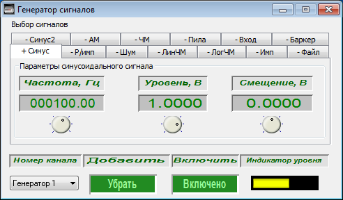
It is necessary to measure the generator signal level with “Voltmeter” program – it must be equal to 1,000 mV.

Add “sine2” signal (“sine” signal should be temporarily removed) in the “Generator” program and set frequency to 300 Hz and a level to 0.1 V.
It is necessary to measure the generator signal level with “Voltmeter” program – it must be equal to 100 mV.

Next, add “sine” signal again in order to measure the THD in “THDA” program. The measurement results must be compared with the results of THD calculations according to a formula:

In the example set above, THD should result 10% or 20 dB (you can switch between the calculation results indicated in percentage or decibels by ticking “lin/log” boxes).
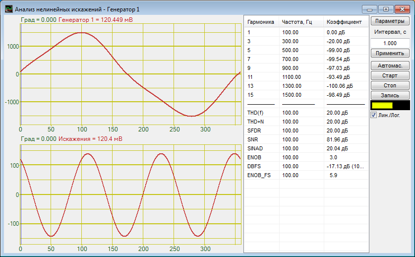
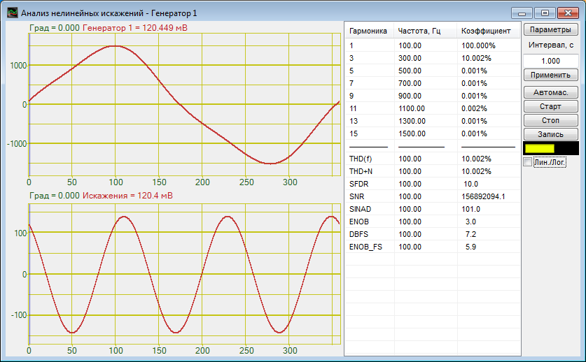
The range of measurement error must be at 0.1% or 0.01 dB.
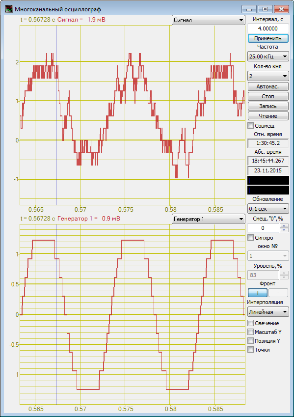
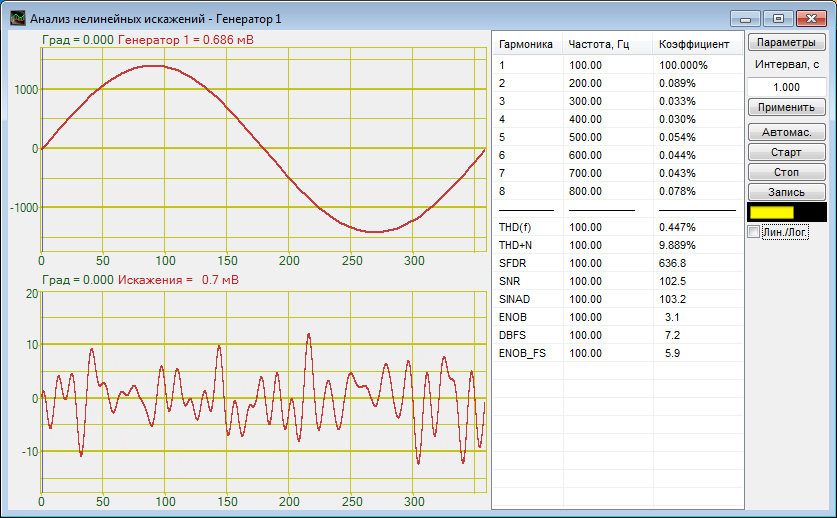
Due to limited number of ADC and DAC bits (ADC – measuring channels, DAC – generators) the accuracy of measurement results will increase with a decrease in signal power capacity. Spectrum analyzer digital resolution is approximately 0.3 mV. Furthermore, RMS value of measuring channels nonremovable noise is approximately 0.25 mV.

For example, for a sinusoidal signal of 1 mV rms, and the level of the third harmonic of 0.1 mV the results are as follows.
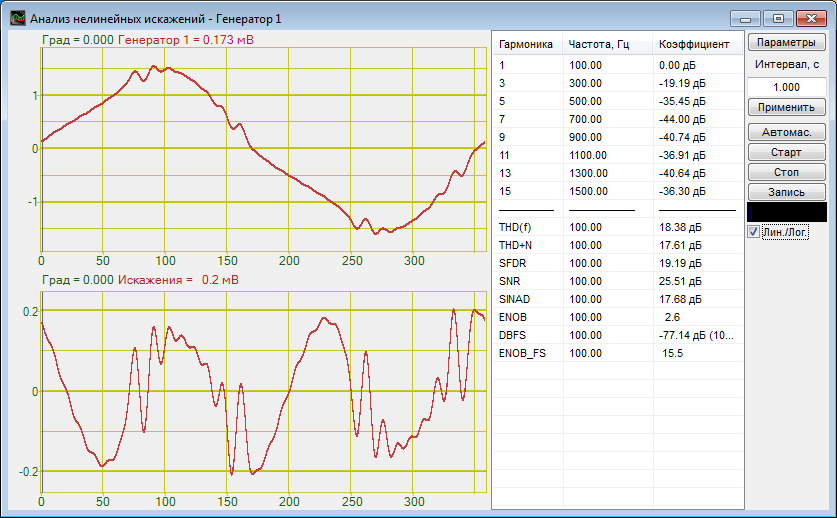
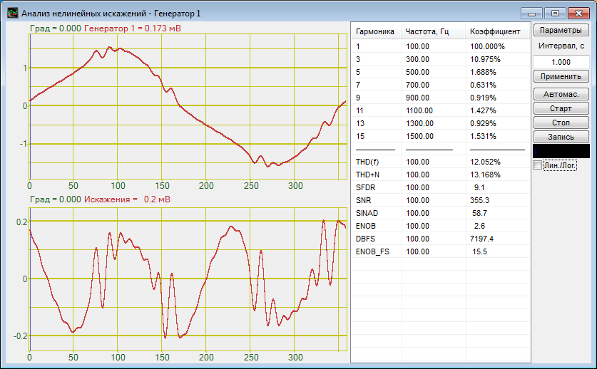
Thus, we can conclude – the more powerful signal we measure, the lower is the measurement error.
Second example
For standard signals, THD can be calculated analytically. Thus, you can set standard signals using the generator program and compare the measurement results with the results of calculations.
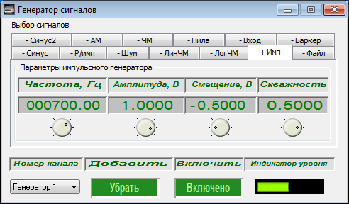
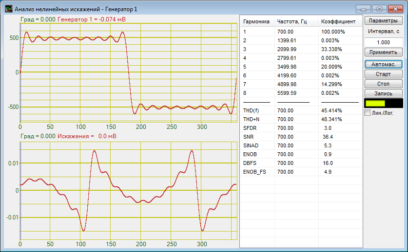
The symmetrical rectangular signal (square wave) is 48.3% THD.
In order to obtain a symmetrical rectangular signal to add the “impulse” signal in the generator program and set frequency to 700 Hz, amplitude to 1 V, shifting to 0 V and pulse ratio to 0.5.
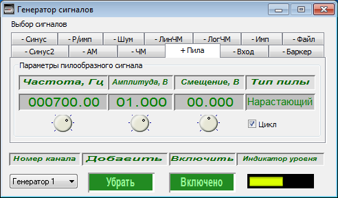
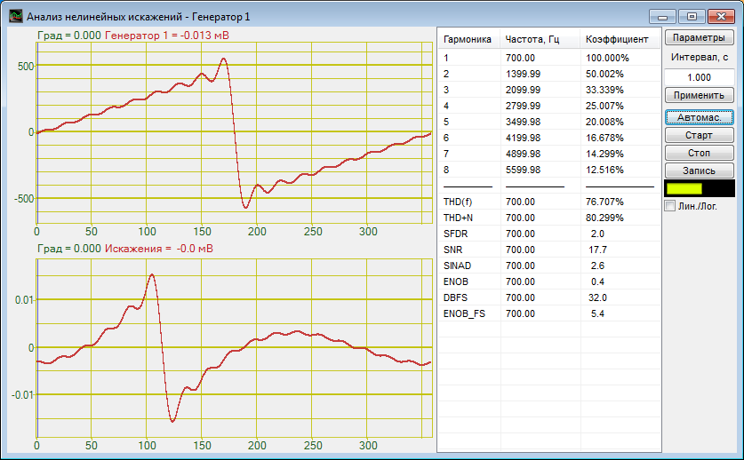
The ideal saw-tooth signal has THD of 80.3%.
In order to get the ideal saw-tooth signal to add “saw” signal in the generator program and set frequency to 700 Hz, amplitude to 1 V, shifting to 0 V and choose decreasing or increasing type.
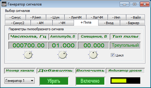
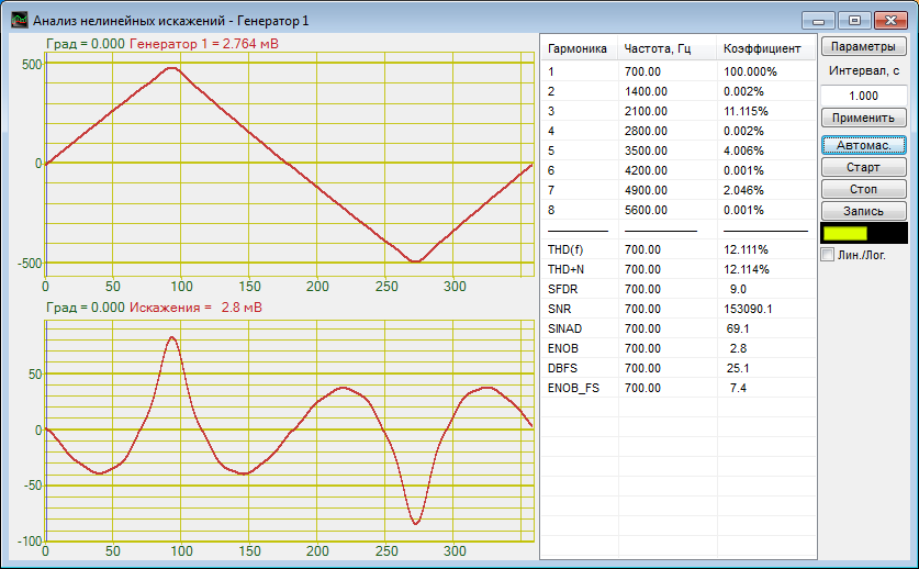
Symmetrical triangle-shaped signal has THD of 12.1%.
In order to obtain a symmetrical triangle-shaped signal to add “saw” signal in the generator program and set frequency to 700 Hz, amplitude to 1 V, shifting to 0 V and set type to triangle-shaped signal.
SNR (Signal-to-noise ratio) Evaluation
Add “sine” in the generator, set frequency to 100 Hz, level to 1 V and turn on the generator. The voltmeter should read 1,000 mV. This will be the signal value — S.
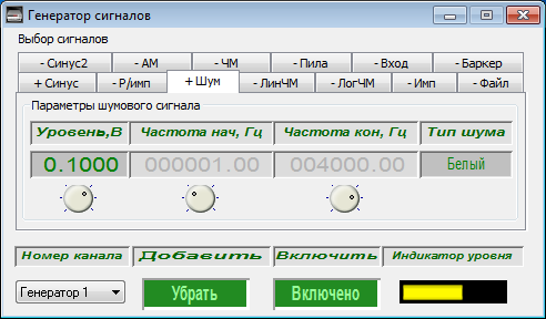
Then remove “sine” and add “noise”, set level to 0.1 V, set the type of noise to “white.” The voltmeter should read approximately 100 mV. This will be the value of the noise — N.

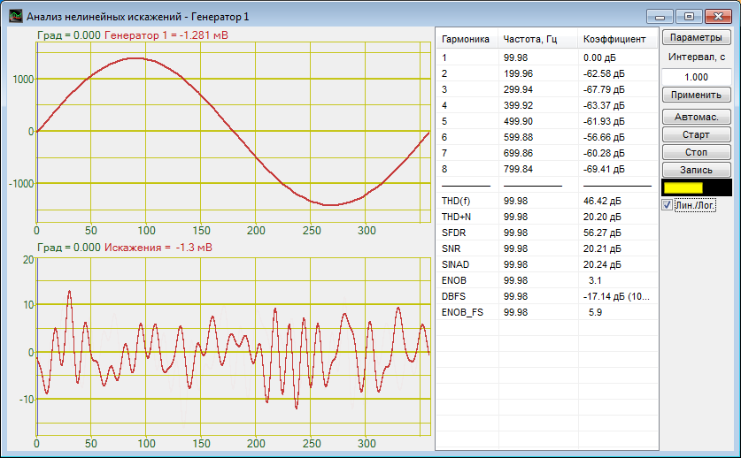
Then add “sine” again and measure the sum signal by means of “THDA” program. The measurement results obtained from the “THDA” program must be compared with the results of SNR calculations according to a formula.

For the parameters set above, SNR signal should be 20 dB or equal to 100 (i.e. energy of the signal is 100 times bigger than the noise power).
Variations of the measurements caused by randomness in the noise should not exceed 0.5 dB or 5 times.
THD + N (Total harmonic distortion and noise) Evaluation
Add “sine” in the generator, set frequency to 100 Hz, level to 1 V and turn on the generator. The voltmeter should read 1,000 mV. This will be the signal value — S.
Then, remove the “sine” and add “sine2”, set frequency to 300 Hz, level to 0.1 V, set the type of noise to “white.” The voltmeter should read approximately 100 mV. This will be the value of distortion — D.
Finally, it is necessary to remove the “sine2” and add “noise”, set level to 0.1 V, set the type of noise to “white.” The voltmeter should read approximately 100 mV. This will be the value of the noise — N.
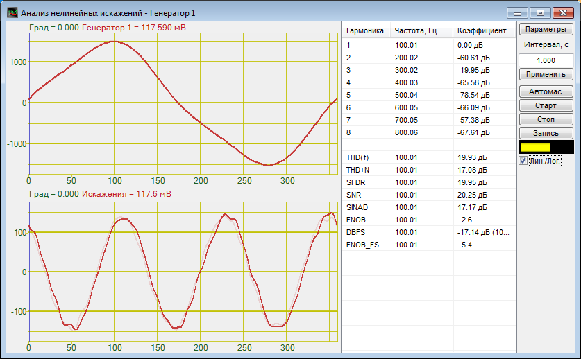
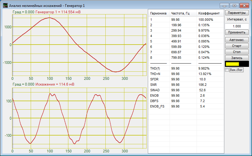
Next, re-enable “sine” and “sine2” and measure the total signal in the “THDA” program. The measurement results obtained from the “THDA” program must be compared with the results of THD + N calculations according to a formula

For the signal parameters indicated above, THD + N should be equal to 17 dB, or 14%.
Variations of the measurements caused by randomness in the noise should not exceed 0.5 dB, or 0.5%.
THD and SNR should be equal to 20 dB or 10%.
SFDR (Spurious-Free Dynamic Range) Evaluation
Add “sine” in the generator, set frequency to 100 Hz, level to 1 V and turn on the generator. The voltmeter should read 1,000 mV. This will be the signal value — S.
Then, remove the “sine” and add “sine2”, set frequency to 300 Hz and level to 0.1 V. The voltmeter should read approximately 100 mV. This will be the value of the third harmonic — U3. In addition, this signal will be the only harmonic.
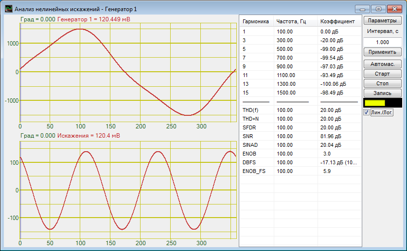
Next, re-enable “sine” and measure the sum signal in the “THDA” program. The measurement results must be compared with the results of SFDR calculation according to a formula:

For the signal parameters indicated above, SFDR should be equal to 20 or 10 dB (i.e. fundamental harmonic is 10 times bigger than the maximum of harmonic distortion).
Measurement error must not exceed 0.01 or 0.1 dB.
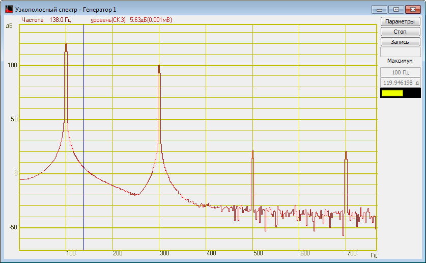
For a visual representation of the SFDR calculation results, it is necessary to run the “Narrowband spectrum” program and set “Calculating values on Y” to “logarithmic, dB”. SFDR value can be easily calculated in this case, as the difference between the peak value of the fundamental frequency and the highest peak value at the harmonic frequency.
SINAD (Signal-to-noise and distortion ratio) Evaluation
Add “sine” in the generator, set frequency to 100 Hz, level to 1 V and turn on the generator. The voltmeter should read 1,000 mV. This will be the signal value — S.
Then, remove the “sine” and add “sine2”, set level to 0.1 V, set the type of noise to “white.” The voltmeter should read approximately 100 mV. This will be the value of distortion — D.
Finally, it is necessary to remove the “sine2” and add “noise”, to set level to 0.1 V and set the type of noise to “white.” The voltmeter should read approximately 100 mV. This will be the value of the noise — N.
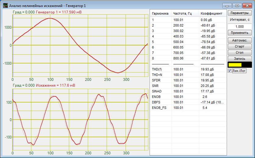
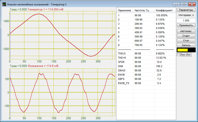
Next, re-enable the “sine” and “sine2” and measure the sum signal in the “THDA” program. The measurement results obtained from the “THDA” program must be compared with the results of SINAD calculations according to a formula

For the signal parameters indicated above, SINAD should be equal to 17 dB or 50 times.
Variations of the measurements caused by randomness in the noise should not exceed 2 dB or 0.5 times.
ENOB (Effective number of bits) Evaluation
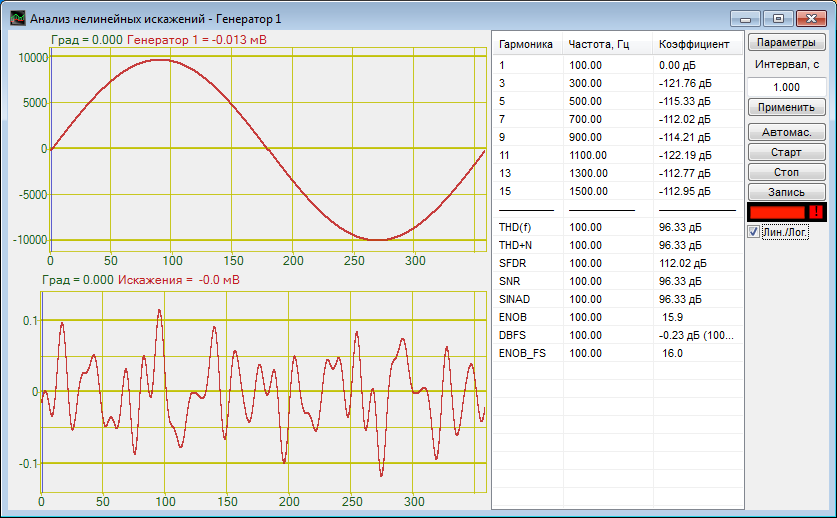
Add “sine” in the generator, set frequency to 100 Hz, level to 7.0 V and turn on the generator. The voltmeter should read 7,000 mV.
Next, measure the signal in the “THDA” program. The measurement results obtained from the “THDA” program must be compared with the results of ENOB calculations according to a formula:

Since the bit depth of ZET017 analyzer is 16 bits, ENOB cannot exceed 16 bits. For the parameters indicated above, on the tested ZET017 analyzer, the result of ENOB calculations should be 15.5.
The ENOB features include bit ranking (bit ranking, like normal data bit, increases the range 2 times), and the quantization error of ideal “ADC”.
Since SINAD values are used during ENOB calculations, then the ENOB value of measuring channels is less because of the noise presence.
The formula for ENOB calculation is the inverse formula for calculation of the dynamic range:

Conclusion
In conclusion, it should be noted that in some cases the above-mentioned characteristics can be measured with a different reference level. In this case, pay attention to the identification and use reference books.
dBFS (“Full Scale” in English) is a reference voltage corresponding to the full scale of the device; for example, “record level is -6 dBFS». For a linear digital code, each bit corresponds to 6 dB, and the maximum possible recording level is 0 dBFS.
dBc (“дБн” in Russian) is a reference level of radiation at the carrier frequency or the level of fundamental harmonics in the signal spectrum. Examples of use: “the level of the transmitter side radiation at the frequency of the second harmonic is -60 dBc” (i.e., power of the side radiation is 1 million times less than the carrier power) or “distortion level is -60 dBc.
Due to the fact that the input signal is not always will occupy the whole available dynamic range it was necessary to add a feature (or several features), which would reflect the potential of the ADC.
DBFS is a dimensionless quantity, equal to the ratio of the fundamental harmonics amplitude (S) to the maximum measurable level of the ADC (M). It should be noted that this value is almost always less than 0 and is equal to 0 only when the amplitude of the signal fills the dynamic range of the device.

ENOBFS is a maximum number of bits that can be used in ADC/DAC. This characteristic shows the value close to the real bit ADC/DAC regardless of signal power capacity.

Example test
You have to add “sine” in the generator, set frequency to 100 Hz, level to 3.6 V and turn on the generator. The voltmeter should read 3,600 mV RMS and 5,091 mV amplitude.
DBFS characteristic must be equal to -6 dB.
ENOBFS characteristics should be exactly 1 point more than the ENOB characteristics.
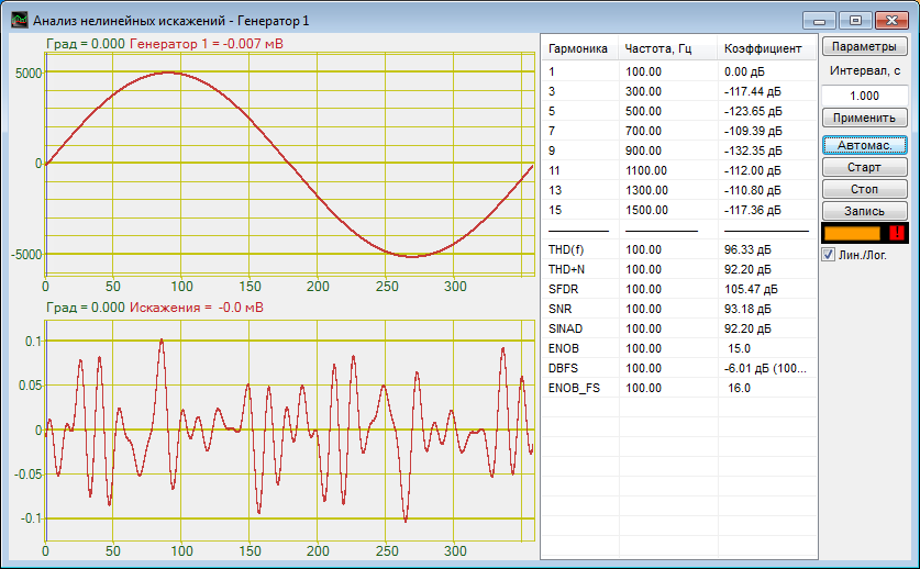
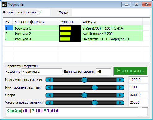
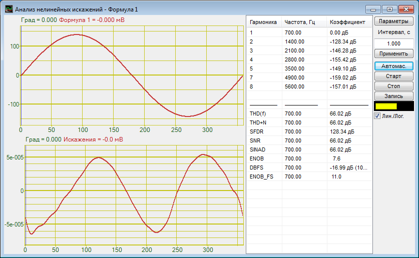
ZETLAB software has the “Formula” program, intended for data processing in accordance with given formulas (including signal generation). Virtual channels created by the “Formula” program (as well as other virtual channels), transmit data in FLOAT-format (32-bit fractional number with floating point according to IEEE 754 standard), which allocated 22 bits to the mantissa. Therefore, for the “Formula” program channels the ENOB value will not exceed 22. The maximum value for ENOB and ENOBFS in “THDA” program is limited to 32.
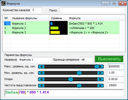
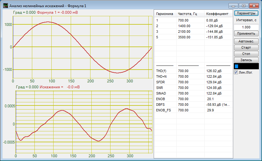
If parameters set for the “Formula” channel significantly correspond with the small dynamic range, the values of ENOB and ENOBFS characteristics will be limited to channel parameters. For example, for the channel with a minimum level of 1 mV (digital resolution) and a maximum level of 1,000 mV (maximum amplitude) the number of allowable values will be 2,000 and 11 bits will be enough in order to encode this channel.
