Diagnostics of gear units
Based on order normalization
One of the convenient and effective ways to diagnose and balance rotating mechanisms, gear units is application of the order normalization.
Subject to availability of a RPM sensor and vibration pickups it is possible to examine temporal characteristics of the gear unit’s vibration signals. Experience has shown that the signal of vibration pickup is noise-contaminated by the signals from other sources. In order to tune out from the interfering signals, a synchronous signal storage method is implemented. During each shaft rotation, the RPM sensor gives a mark point of rotation. This signal is an initiating gate for sweeping of the vibration pickup’s signal. The obtained signal sweepings are summed up. At the same time, all sources of signals connected with the shaft frequency (frequency of revolutions) are accumulated and increased in a summarizer linearly proportional to the number of revolutions N. All remaining signals uncorrelated with the shaft frequency are accumulated proportional to N1/2 and subject to a large number of averages the useful signal exceeds the interference level.
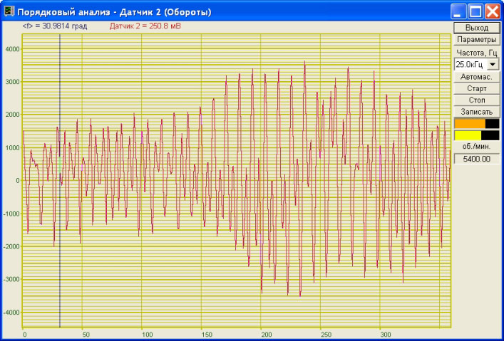
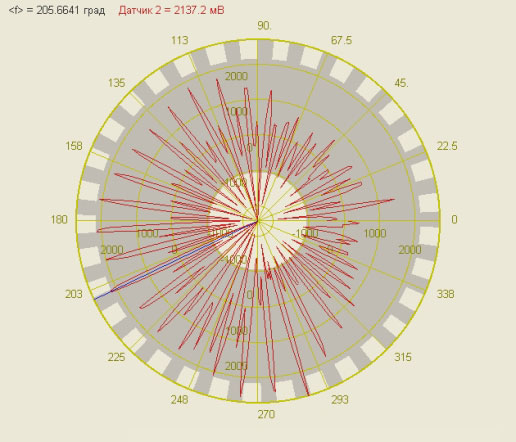
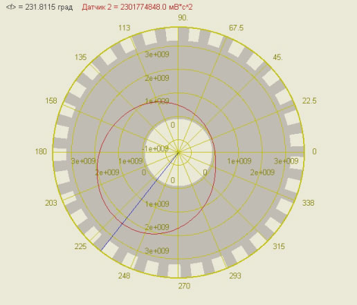
For example, Figure 1 shows the vibration acceleration — a result of synchronous accumulation of vibration pickup’s signal within the frequency range up to 10 kHz. Figure 2 contains a graph of vibration acceleration in polar coordinates with overlaying of the image with gear unit on the graph (gray color). From such image, it is immediately obvious, at which phase of rotation angle the beats appear upon interlocking or unlocking of the gear pair. Starting from the angle of 90 degrees and up to 280 degrees vibration upon interlocking of the gear pairs can be observed, while the remaining sector has vibration upon unlocking. In order to study the cause of vibration let’s evaluate the parameters of vibration displacement and in polar coordinates (Figure 3). The out-of-balance condition of drive shaft can be inferred by Figure 3. This Figure also allows defining the parameters for the shaft balancing.
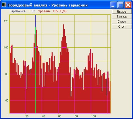
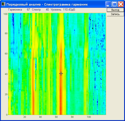
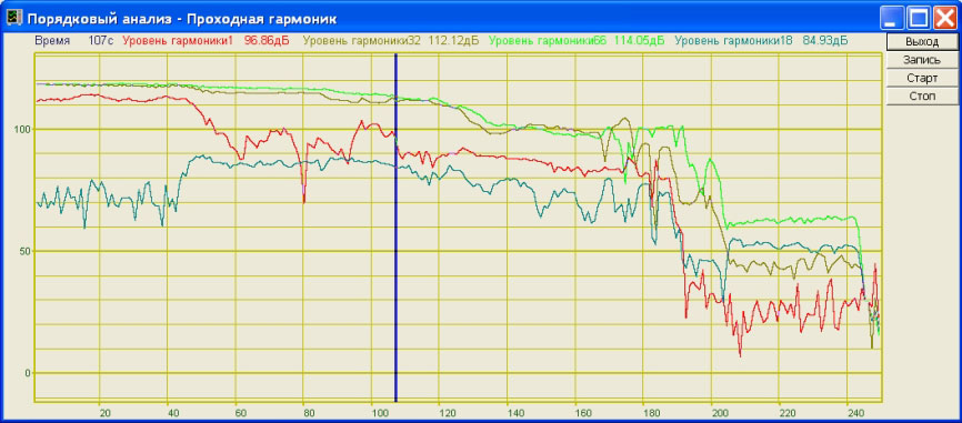
Fourier series expansion of the signal obtained during one revolution of the shaft allows gaining the vibration levels for each shaft speed harmonics. Figure 4 shows the signal spectrum up to 120-th harmonics. The tooth harmonics can be seen on the spectrum. The first harmonics is equal to the number of teeth. Image of the spectra in time in the form of a spectrogram allows (Figure 5) monitoring the changes in oscillation harmonics over the time. Image of the level of selected harmonics in time sweeping (through characteristics, Figure 6) allows controlling the degree of gear pair aging or the beginning of gear pair destruction according to the signal level under the strength tests.
See also:
- diagnostics of gear units;
- diagnostics of gear units based on spectrum of vibration signal;
- diagnostics of gear units based on super narrow-band spectrum;
- diagnostics of gear units based on co-spectrum characteristics;
- diagnostics of gear units based on inter-correlation characteristics;
- diagnostics of gear units based on spectrum of envelope curve.

