Automation of Experiments
With application of digital signal processing methods illustrated based on a vibration source space coordinates determination system taken as example
When solving any task related to research studies, a developer sooner or later faces a challenge of practical implementation of his scientific studies or fulfillment of his tasks in complex tests or automation experiments. This very stage of development lifecycle is dragged out for indefinite time, what naturally entails unwanted financial costs, and the longer this stage is, the larger, in many senses, the losses are, and the less ideas can be implemented. But time of system building can be minimized by means of modular software and hardware solutions.
For example, there is a task to build a system capable of: comprehending information of the controlled object status; processing the input signal (or something that mathematicians usually call a function) [1]; performing mathematical processing of this signal with the subsequent output of controlling signals and recommendations to operator.
This sort of tasks can be easily solved using ZETLab hardware and software which contains around 100 virtual instruments with various functions as well as a wide range of features allowing to solve complex tasks of data collection and processing. Most importantly, nowadays there is hardly a sensor (primary transducer) that could not be connected to ZETLab, and as we all know, a sensor is eyes and ears of any system.
Let’s consider a task of determining spatial coordinates of vibration source or a noise source as a case study demonstrating features of both hardware and software (mathematical) part. To make the task a little more difficult, we will mention that it is a low-intensity source with a similar or even lower level of background noises. For example, these can be man-made noises (highway, railways, pumping station engines, interference of industrial network 50 Hz, etc.), natural noises (purl of water) which neither can be canceled nor banned. However, by using ZETLab mathematical complex you can extract a useful signal of your interest.
Let us consider the following case: there is a certain territory where it is necessary to control and detect unauthorized access, for example, digging. If there is a breach, it is necessary to try to determine the coordinates of this place. The system consists of:
- BC 1313 seismic sensors identifying vibration of soil;
- communication lines transmitting a signal from sensors to measuring equipment;
- recording measuring equipment – ZET 048 seismic recorder;
- operator console – PC.
To solve the task we will use a scientific approach and analyze the particular parameters of the system that can indirectly inform us of unauthorized access.
Stage 1, theoretical calculations. In the place of vibration (or noise) there are formed seismic waves that spread in all directions (Fig. 1, 2), and as soon as they reach seismic sensors, the spreading wave affects the sensors. It is experimentally proved that transversely oscillating waves make maximum energy contribution to the signal (Fig. 3), therefore the used sensors have only one sensitivity component and are installed vertically — on the ground (or horizontally — on the wall). Then, by means of ADC the signal from sensors is digitized and sent to input of location algorithm. So, proceeding from preliminary theoretical calculations, let’s make a flowchart of data flow from the bottom level to operator:

Figure 1. Flowchart of system data flow
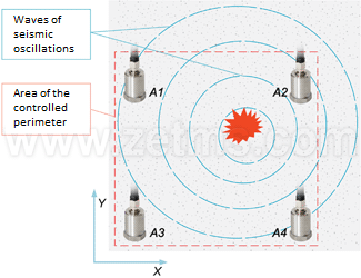 Figure 2. Experiment diagram |
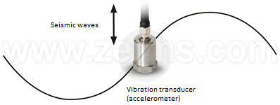 Figure 3. Spreading of transverse waves |
The basis of the used algorithm of the passive location of vibration (noise) sources is determining difference of wave arrival delays to different registration posts located (preferably) around the perimeter of a protected facility, using mutual correlation analysis and formula
![]()
where B12 — function of cross-correlation between sensors 1 and 2, etc., listing all selected sensor pairs [2].
Actually, at the first stage Figure 2 describes an ideal model and the key condition – presence of ambient noises – was omitted. Let’s modify experiment layout (Fig. 4) where highway and railways are specially highlighted.
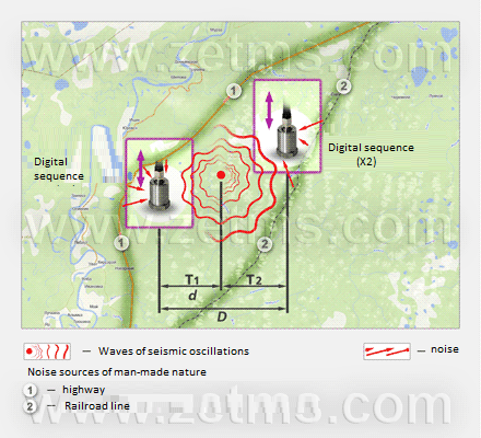
Figure 4. Diagram of the near-total-realism experiment environment
Stage 2. Let’s examine a temporary signal implementation when soil is affected near one of the sensors (signal oscillogram, Fig. 5). Thus, we will verify integrity of communication lines and system configurations. Let’s analyze frequency components of a signal, in other words, a frequency spectrum, and estimate effect of ambient noises on sensors when a useful signal is available and unavailable (Figure 6 illustrates the entire frequency range, no analysis is performed in this case in the narrow frequency bands, Figure 7 illustrates the detailed spectrum).

Figure 5. Impact on soil close to one sensor
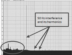
Figure 6. Impact of useful signal is reflected in the low-frequency area

Figure 7. Signal before and after digital filtering (adaptive filter 50 Hz and band filtering 10…100 Hz)
To clear the spectrum of seismic sensor signal from 50 Hz interference and its harmonics, let’s use software implementing an adaptive filtering algorithm, which is a part of ZETLab kit (during the adaptation, some corrections are automatically added to the algorithm together with feedback for the purpose of optimizing system performance parameters [3])
Choosing cut-off frequencies of band filters ensuring frequency filtering not related to the useful signal. Studies of the useful signal spectrum (Fig. 6) show that waves within 10…100 Hz frequency range make maximum energy contribution to the signal, while the restriction on the upper frequency relates to rapid attenuation of soil oscillation waves (in other words, wave absorption). The restriction on low frequencies associates with wavelengths and the distance where we are carrying out measurements. Let’s assume that protected perimeter is 500×500 m, speed of wave spreading in soil (sand-soil mixture) is approximately v = 1000 m/s (actually, the wave speed depends on soil quality), wavelength λ = v/υ, therefore, a wave with frequency of υ = 0.1 Hz will be 10 k long, and it is obviously too much for the 500 meter zone. Naturally, this kind of waves will have an impact on a signal researched. At the same time, a wave with the frequency of υ = 10 Hz corresponds to 100 m, which is quite acceptable. Let’s estimate the benefit of a signal that underwent digital processing by ZETLab if compared to its source signal. Signal dispersion before processing is 1 mV, after processing – 0.2 mV, we see a five-time difference (or 20 lg5 = 14 dB) what is more than significant. And only now we use the correlation analysis formula
![]()
to get an adequate result based on which we can identify the direction to the vibration source. The function of mutual correlation between two seismic sensors is shown in Figure 9, where the correlation peak is shown with the line. This peak may appear due to the effect of the searched object on soil, but it is impossible to check it at this stage.
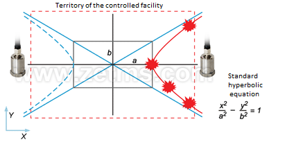
Figure 9. Function of mutual correlation between two sensors
Stage 3. Let’s assume that time delay corresponding to a maximum correlational peak, when expressed in equivalent to distance, will actually result in the coordinate of the vibration source. Let’s express the time delay in equivalent to the coordinate along a straight line between sensors. However, remember that mutual correlation function shows only a difference of wave arrival at two registration points. If we consider the mutual location of the possible coordinates, they are described by hyperbola equation (Fig. 10).
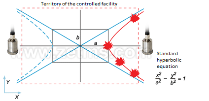
Figure 10. Area of equiprobable coordinates of the vibration source is described by hyperbola equation
Therefore, it is impossible to address the task using only two sensors. But three sensors are sufficient to get an acceptable solution. The example diagram shows four sensors, which enable considering six correlational pairs and significantly increase coordinate determination reliability. Then the counts of correlation functions of each sensor pair with a respective time delay are compared to each point of XY-plane by the reverse projection method, and a two-dimensional array is formed. Each element of the array corresponds to a certain range of protected perimeter and contains “energy contribution” of this area to the overall noise level. A similar calculation of a two-dimensional array occurs for each correlational pair and sums up with previous arrays. The algorithm result is a graphical representation (XY-gram) where a place corresponding to the coordinate of the noise source effect on the soil of protected perimeter is gradually shown. The functional layout of the experiment is shown in Figure 11, and the algorithm result is shown in Figure 12.
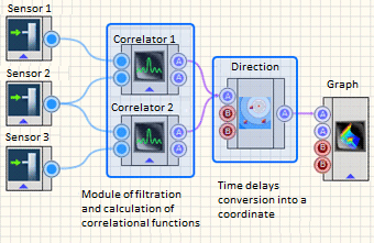 Figure 11. Functional flowchart of location algorithm |
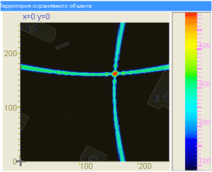 Figure 12. Location algorithm operation result (from three sensors and two correlation functions) |
The resulting algorithm is based on interference filtering, accumulation of “energy” obtained from each point of space, and its representation. Unlike traditional methods of determining object bearing, this algorithm considers the effect of all correlational function values, since Δt of maximum correlational peak actually does not correspond to the time delay of seismic wave arrival at sensors from the searched object. Due to the absence of binding to a certain correlational peak, this method has an advantage of several targets simultaneous tracking, which is very important for solving real location-related tasks. Thus, the main advantages of this system based on ZETLab hardware and software are as follows: high sensitivity, fast localization time, precise coordinates determination, monitoring of several objects, high reliability, high process automation, and real-time detection.
The article is published in the “Industry Automation” journal, No.6, 2009
Author: A. Krasovsky
References:
Gribunin V.G. “Digital signal processing glossary”;
Sergiyenko A.B. “Digital signal processing”;
Widrow B., Stiriz S. “Adaptive signal processing.”
