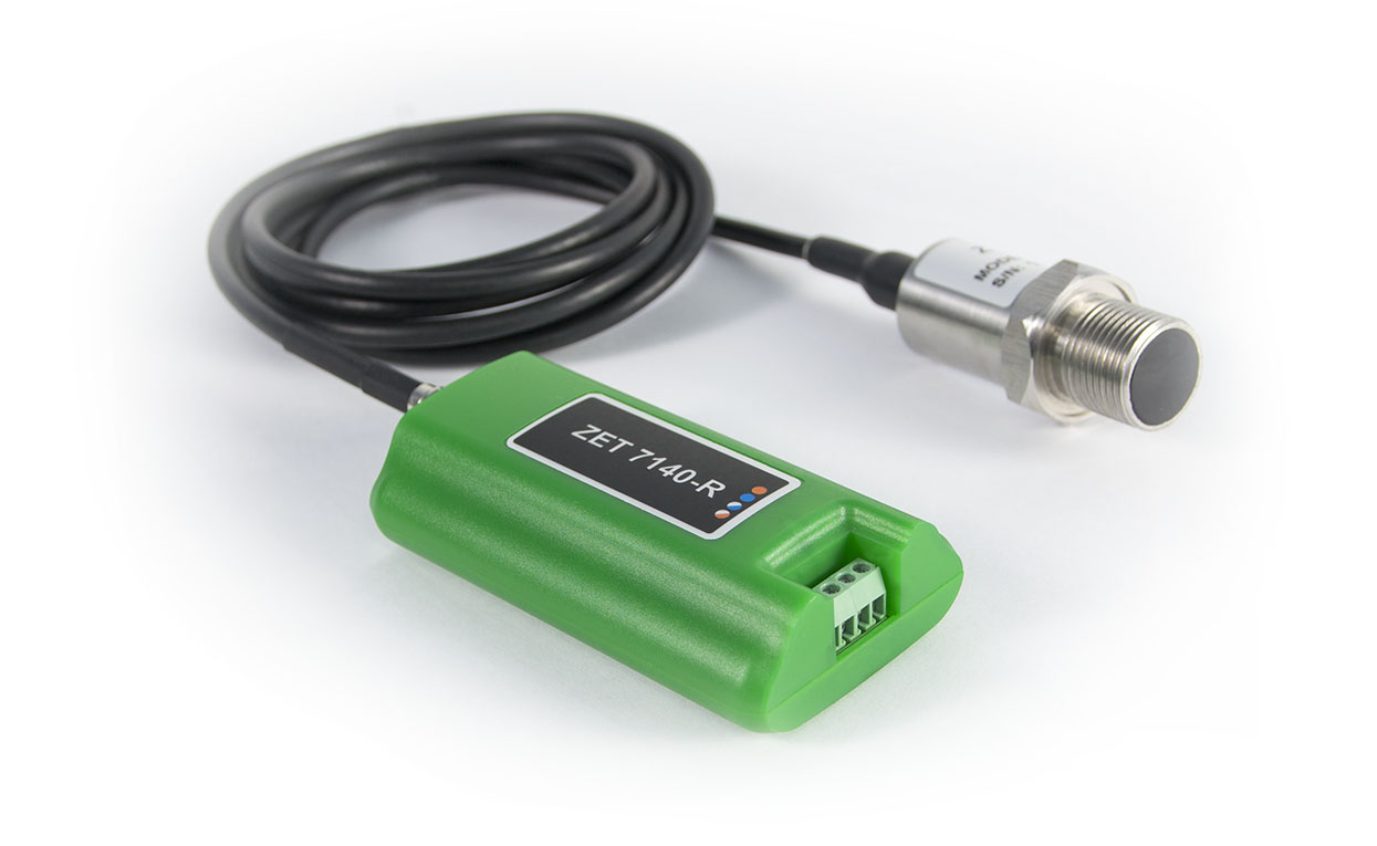
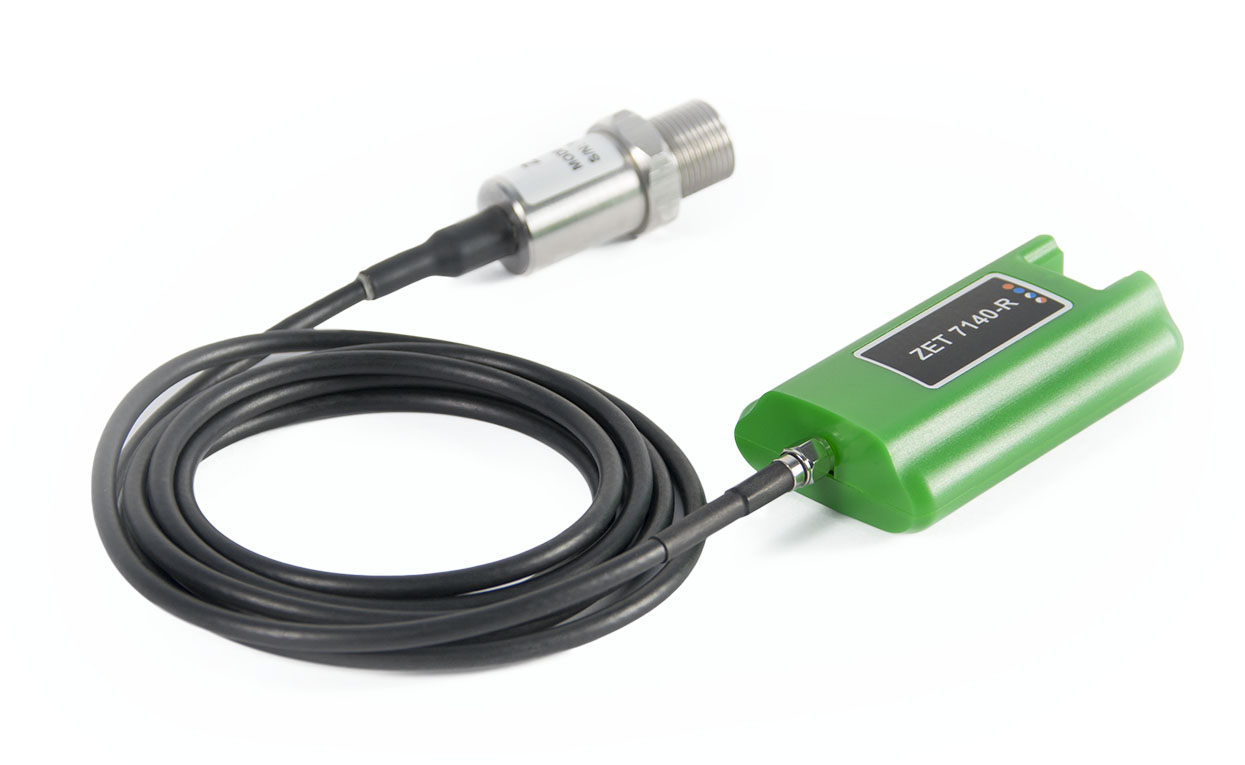
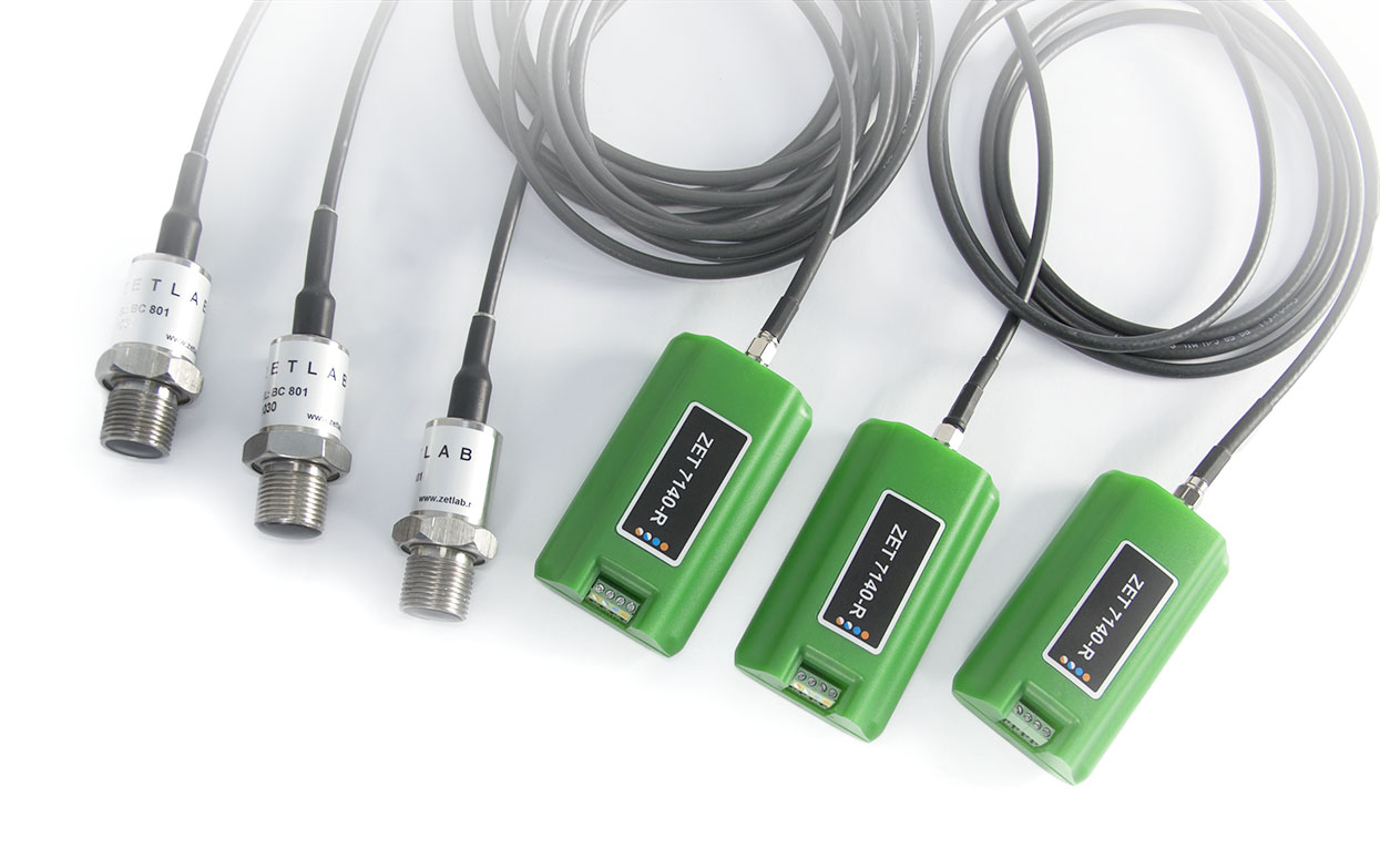
ZET 7140-R Digital Cavitation Sensor

  • Data transmission interface CAN 2.0
  • Amplification 10
  • Input range ±100 mV
  • AD converter bit depth 14 bit

From 1602 USD

Specifications

of the ZET 7140-R Digital Cavitation Sensors

Metrological Data
Rated sensitivity 22 µV/Pa
Frequency band 3 ~ 160 000 Hz
Technical Specifications
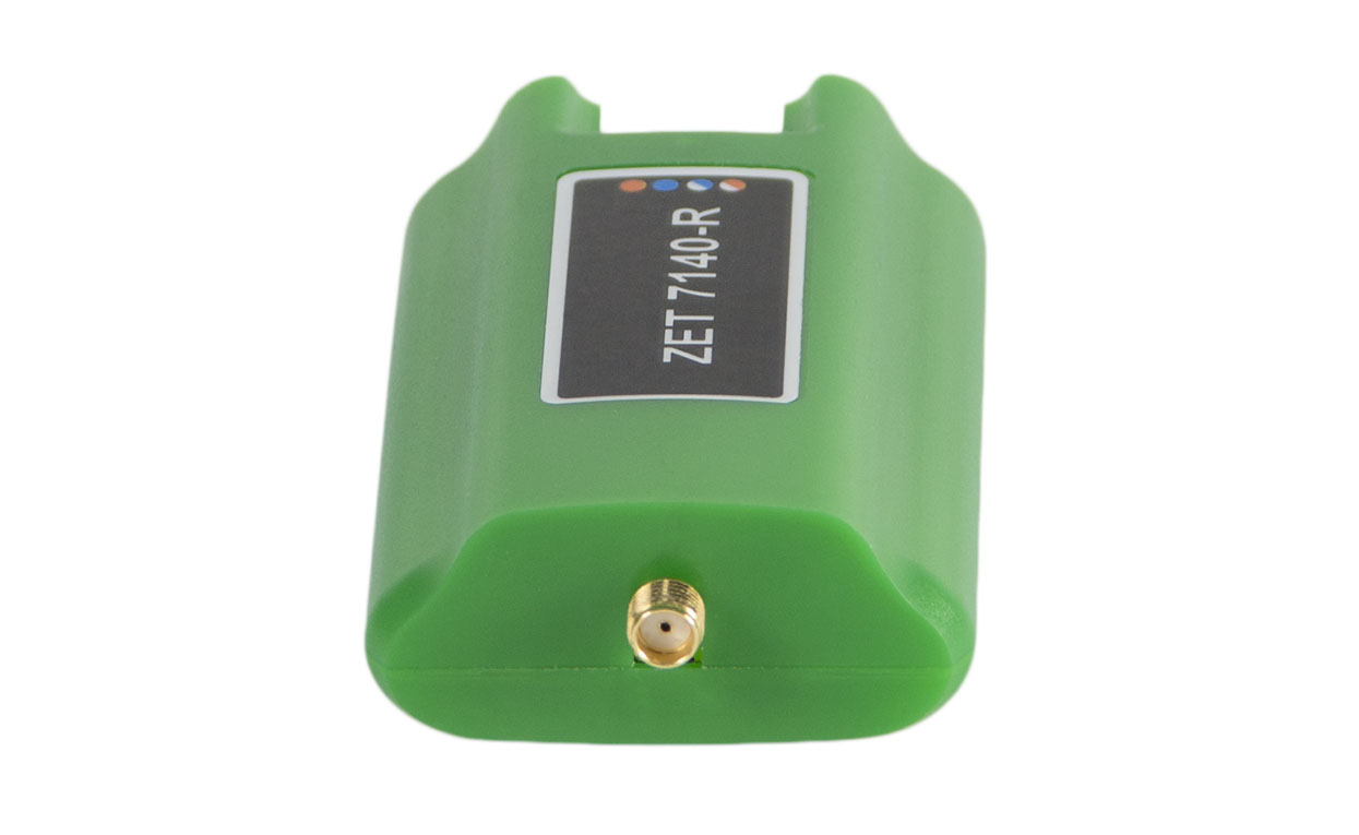
Socket type for connecting a primary transducer SMA
Measured parameter RMSD of the signal from the primary transducer
Data output frequency 1, 10, 100 Hz
Measurement range depends on type of the primary transducer
Data transmission interface CAN 2.0
Amplification 10
Input range ±100 mV
AD converter bit depth 14 bit
Sampling rate 1.2 MHz
4 kV electrostatic discharge input protection yes
Inputs overvoltage protection (current shall not exceed 10 mA) yes
Performance Specifications
Dimensions 83×37×14 mm
Weight 40 g
Power supply 9 to 24 V
Consumed power 1.5 W
Operational temperature range -40 to +100 °С
  • Hardware Versions

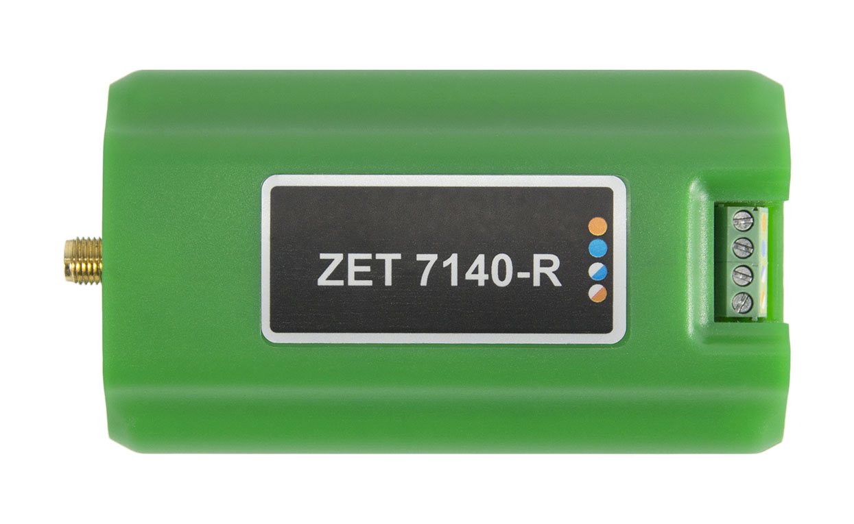
    Standard: laboratory design in a plastic cover (green)
    ОЕМ: board covered with a sealing compound.
    Heavy Duty*: unit of standard design in an air-tight cover
    (with a transparent lid)
    *Option

Advantages

of the ZET 7140-R Digital Cavitation Sensors

No Adjustment is Needed

The characteristics are stored in the measuring unit memory

Measurement Results

Measurement results are transmitted in a digital form

Power supply

Primary transducers are powered by the measurement unit

Reliability

Stable characteristics and high reliability in operation

Operation Principle

of the ZET 7140-R Digital Cavitation Sensors

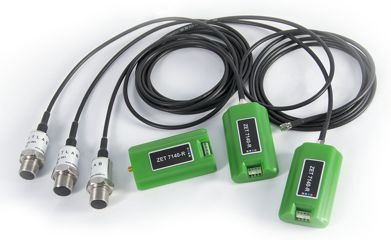
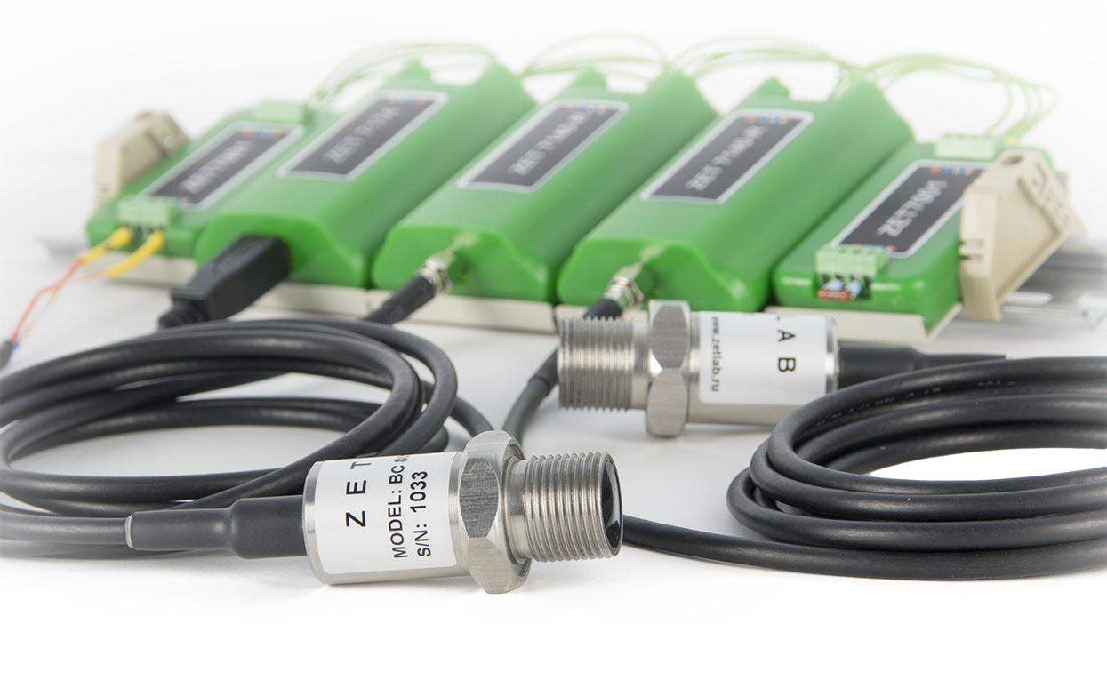
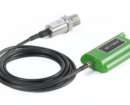
Digital cavitation sensor design includes a primary transducer (a transducer with a sensing element made of ceramic piezoelectric materials) and a measuring unit (ZET 7140-R).

The primary transducer is installed on the object to be studied and connected to the measuring unit. The measuring unit performs analogous-digital conversion of the signal from the transducer to the vibration parameter values. The measurement results are transmitted via CAN interface.

The characteristics of the primary transducer are set in the device memory and measurements are performed with those parameters taken into account.

Thus, the use of digital sensors releases the user from the necessity of the measuring channels setting and data processing.

Purpose

of the ZET 7140-R Digital Cavitation Sensors

  • Erosion Assessment

  • Erosion - Operation Mode Dependency

  • Turbine Cavitation Characteristics Improvement

  • Erosion Forecasting

  • Change Tracking, Accidents Discovery

  • Turbine, Hydro Power Plant Operation Optimization

Cavitation is formation of cavities filled with gas, vapor, or mixture thereof, in a flowing liquid.

Cavitation leads to pressure surges, acoustic radiation, and, sometimes, to dangerous vibrations of the machine.

Consequences of cavitation are directly visible during maintenance. So, it is best of all to observe the object in real time to determine the source of erosion and to find answers to such questions as: “what working points are subjected to erosion most of all?” “which parts cause erosion?” Testing in the form of a continuous monitoring are required for tracking the effects of time and discovering changes related to faults. Most often, such objects for observation are turbines, HPPs.

The only practical method of testing and monitoring is the use of cavitation sensors (vibroacoustic sensors) installed on a turbine to listen to the cavitation noise and assess the cavitation effects such as turbine parts vibrations.

Digital cavitation sensors are intended for cavitation processes study, ultrasonic measurements in liquid mediums. The ZET 7140-R measuring unit receives a broadband acoustic signals emitted by the primary transducers and determines the level of cavitation.

Connection Diagrams

of the ZET 7140-R Digital Cavitation Sensors

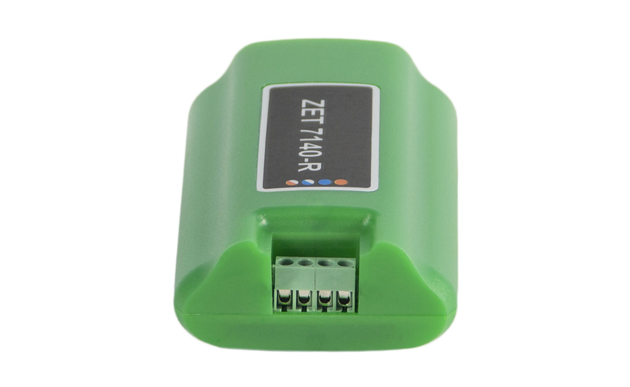
Measuring unit sockets

ZET 7140-R

SMA socket
PT connection

ZET 7140-R

Socket for connection to
the measurement network

Definition of pins for connecting to CAN line

Pin Definition  Marking
1 +(9 ~ 24) V Orange
2 H line of CAN 2.0 Blue
3 L line of CAN 2.0 White-blue
4 GND White-orange

Measurement Network Diagram

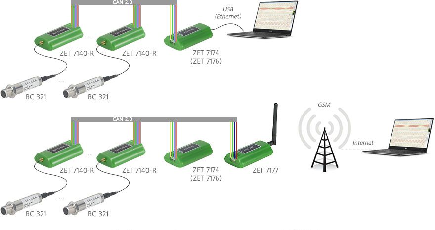
MEASUREMENT NETWORK STRUCTURE:

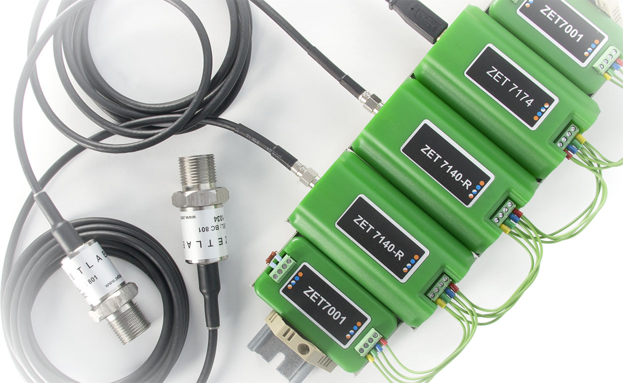
  • Digital cavitation sensor ZET 7140-R
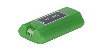
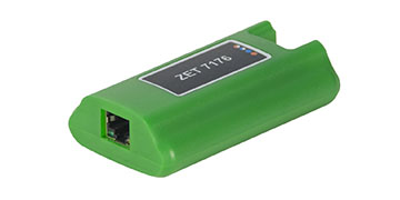
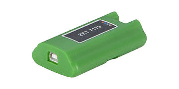
  • ZET 7174 CAN to USB interface converter or ZET 7176 CAN to Ethernet converter;
  • PC with ZETLAB SENSOR software, ZETKEY key for the software activation;
  • ZET 7172M and ZET 7172S units, if wireless data exchange is required.
zet-7140-r-VS321

Test impact types

AC - alternating signal

FR: «Required frequency value»: «Frequency tolerance» – alternating signal frequency;

AM: «Required signal amplitude value»: «Signal amplitude tolerance» – alternating signal amplitude;

OF: «Generated signal bias»: «Generated signal bias tolerance» – generated signal bias;

TM: «Signal analysis time» – signal control time (minimal signal analysis time for transient processes or long-time tests)

Example:
AC;FR:0.5:0.01;AM:0.4:0.002;OF:0.1:0.0001;TM:5
Alternating signal with frequency: 0.5 ± 0.01 Hz, amplitude: 0.4 ± 0.002 V, bias: 0.1 ± 0.0001 V, minimal signal control time – 5 s.

DC - constant signal

LE: «Required signal level»: «Signal level tolerance» – generated signal level.

TM: «Signal analysis time» – control signal time (signal analysis minimal time for transient and long-time processes tests)

Example:

DC;LE:0.5:0.001;TM:5
constant signal: 0.5 ± 0.001 V, minimal signal control time – 5 s.

ST1 - stepwise change

AM: «Minimal value»: «Maximum value» – change range.

TM: «Signal setting time» – time before signal control start

Example:
ST1;AM:100:200;TM:5
stepwise change: for 100..200 units, minimal signal control time – 5 s.

ST2 - stepwise change

MD: «Minimal change»: «Maximum change» – change amplitude.

TM: «Signal setting time» – time before signal control start

Example:
ST2;MD:10:10.5;TM:6
stepwise change: for 10..10.5 units in modulus, minimal signal control time – 6 s.

PPS - Pulse-per-second signal

SP: «Acceptable counts deviation» – amount of counts before or after start of a second.

Level change to be checked one time in a second.

Example:
PPS;SP:2 –
the change should take place in the beginning of a second, 2 counts.

Device type is selected from the dropdown list. In order to select a device, pick an element with left mouse key and choose a device to be checked from the list.

Use selector to set particular test. To set the test number click the number with left mouse key and set the required value by scroll. If the self-check is on, the selector will not be available until the user stops the project or the self-check is over. There is a key for start / stop of the process. The green key means that the diagnostics process is on, grey key stands for  for idle state.

Indicator is a timer showing the elapsing time of the current test. The countdown is started after beginning of any test. Test results are available in the log.

Basic configuration

of ZET 7140-R digital cavitation sensors

ZET 7140-R комплект

Cavitation senspr basic configuration includes:

  • Digital cavitation sensor ZET 7140-R;
  • set of operational documentation.

From 1602 USD

Order form - If you want to place an order or to make a request regarding technical specifications of particular product, fill out the form below:

Necessary measuring equipment

supplied upon special order

ZET 7174
ZET 7174
USB connection

ZET 7176
ZET 7176
Ethernet connection

ZET 7173
ZET 7173
Off-line mode