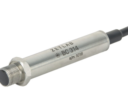
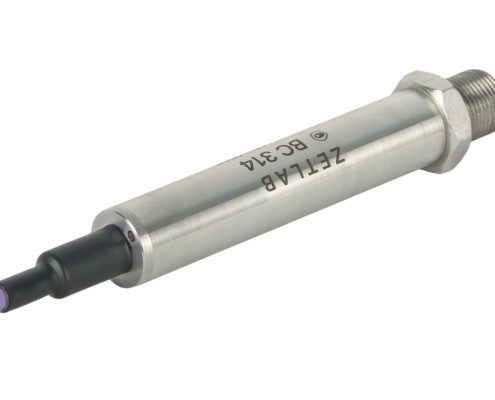
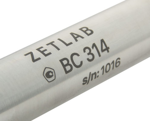
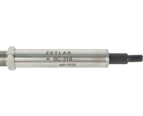
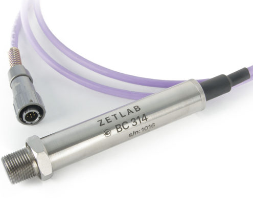
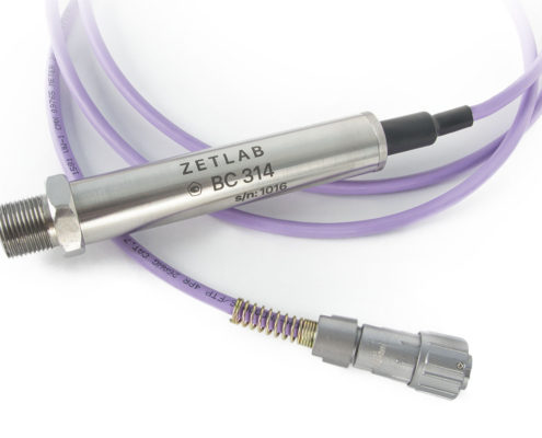
BC 314-M DIGITAL THREADED HYDROPHONE

  • hydrophone with CAN 2.0 digital output;
  • measurement results are transmitted via Modbus protocol;
  • measuring acoustic signals and noise spreading in liquids;
  • used as receiver hydroacoustic antennas components;
  • used for measurements by cutting-in to the wall of sealed vessel or pipe.

POR (price on request)

PURPOSE

of BC 314-M digital threaded hydrophones

MEASUREMENT

  • sounds spreading in water;
  • noise in wet and polluted environment;
  • sound in liquid and gas environment (laboratory and factory).

APPLICATION IN HYDROACOUSTICS

  • monitoring of waterborne sounds;
  • measurement targets.

SPECIFICATIONS

of BC 314-M digital threaded hydrophones

SPECIFICATIONS
Parameter gauged instant values, RMS, peak Pa, kPa
Measuring range 100 kPa
Self-noise*, RMS 0.1 Pa
Frequency band 20…3,200 Hz
Type of transducers connected integrated piezo transducer
Tolerance limit of sound pressure range gauging 10%
Limit measured dynamic pressure 50 kPa
Limit hydrostatic pressure 7 MPa
Data output frequency 12,000, 8,000, 4,000, 2,000, 1,000, 500,
if non-instantaneous values output — 10 Hz
Data interface CAN 2.0
Device power 9 to 24
Current consumption at 12 V voltage up to 50 mA
Reading Frequency Response available (diagnostics)
Sensing element integrity check available (diagnostics)
Power check available (diagnostics)
Synchronization by Precision Time Protocol (PTP)
Casing material stainless steel
Dimensions (length × casing diameter) 171×⌀23 mm
Coupling thread M20×1.5
Weight (without cable)
Cable length 2 m (standard)
Measurements operation environment water, air, oil and oil products, natural gas
Operation environment temperature 0…+60 °C
Environment air temperature −60…+80 °C

Referred to output in frequency band from 10 Hz to the band upper limit.

CONNECTION DIAGRAM

of BC 314-M digital threaded hydrophones

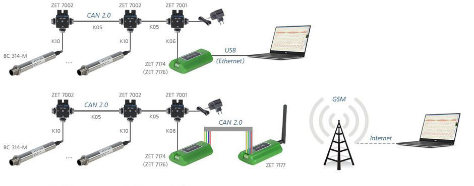
Hydrophone BC 314-M is a digital transducer is used to measure dynamic pressure in liquid environments with CAN 2.0 data interface. Measurement results are transmitted by Modbus protocol. A hydroacoustic antenna can be connected to PC via USB, Ethernet, GSM, radio channel:
Construction-of-measuring-network-BC-314-M-1

Digital hydrophones integrated sensing element allows starting measurements right after it is switched on since the measurement process does not require measuring channel adjustments: all the essential parameters are pre-installed in gauge memory. The output signal of digital transducers contains measured pressure values; no additional processing of the results is required.

Instrument communications network connection

Digital hydrophones BC 314-M have an integral cable without a connector on the side of the measuring network. The diagram of connection to the measuring network is shown in the chart.

CONTACT NUMBER LABELLING CABLE CONDUCTOR COLOUR
1 “+” (9…24) V orange
2 CAN 2.0 line “A” blue
3 CAN 2.0 line “A” white-blue
4 GND white-orange

BC 314-M HYDROPHONES: OPERATION IN RECEIVER MODE

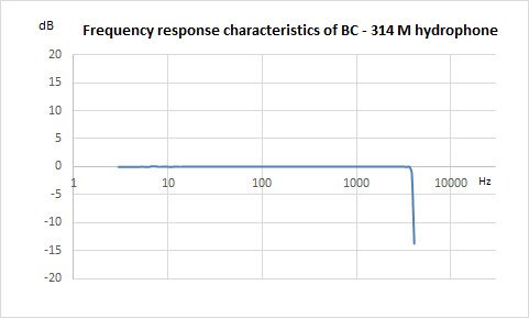
Frequency response characteristics of Hydrophone BC 314-M are shown in the chart

Hydrophone BC 314 - Frequency response characteristics

METROLOGICAL SELF-MONITORING

of BC 314-M digital threaded hydrophones

Hydrophone BC 314-M has a function of metrological diagnostic self-monitoring — the transducer serviceability auto-check in the course of its operation. Based on metrological self-monitoring positive results, it is possible to increase the inter-verification interval without implementing standard verification procedure.

For metrological self-monitoring of ZETSENSOR digital transducers in automatic mode, there has been developed special software.

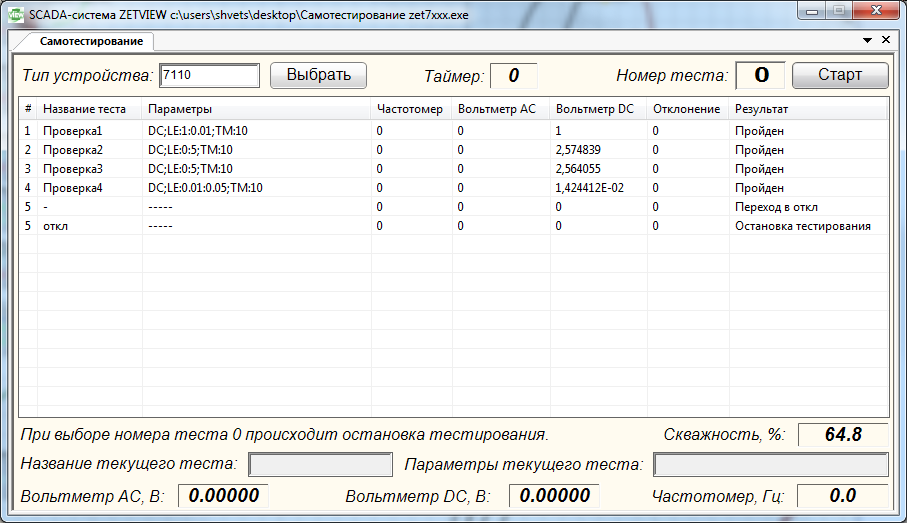
“Self-check ZET 7XXX” main window is shown in the figure. On “Self-check” tab, the user can select a type of device, type of test, measurement process control and view the self-check results.

Metrological self-control

Test impact types

AC - alternating signal

FR: «Required frequency value»: «Frequency tolerance» – alternating signal frequency;

AM: «Required signal amplitude value»: «Signal amplitude tolerance» – alternating signal amplitude;

OF: «Generated signal bias»: «Generated signal bias tolerance» – generated signal bias;

TM: «Signal analysis time» – signal control time (minimal signal analysis time for transient processes or long-time tests)

Example:
AC;FR:0.5:0.01;AM:0.4:0.002;OF:0.1:0.0001;TM:5
Alternating signal with frequency: 0.5 ± 0.01 Hz, amplitude: 0.4 ± 0.002 V, bias: 0.1 ± 0.0001 V, minimal signal control time – 5 s.

DC - constant signal

LE: «Required signal level»: «Signal level tolerance» – generated signal level.

TM: «Signal analysis time» – control signal time (signal analysis minimal time for transient and long-time processes tests)

Example:

DC;LE:0.5:0.001;TM:5
constant signal: 0.5 ± 0.001 V, minimal signal control time – 5 s.

ST1 - stepwise change

AM: «Minimal value»: «Maximum value» – change range.

TM: «Signal setting time» – time before signal control start

Example:
ST1;AM:100:200;TM:5
stepwise change: for 100..200 units, minimal signal control time – 5 s.

ST2 - stepwise change

MD: «Minimal change»: «Maximum change» – change amplitude.

TM: «Signal setting time» – time before signal control start

Example:
ST2;MD:10:10.5;TM:6
stepwise change: for 10..10.5 units in modulus, minimal signal control time – 6 s.

PPS - Pulse-per-second signal

SP: «Acceptable counts deviation» – amount of counts before or after start of a second.

Level change to be checked one time in a second.

Example:
PPS;SP:2 –
the change should take place in the beginning of a second, 2 counts.

Device type is selected from the dropdown list. To select the device type you have to left-click the element and to select the required device to be checked from the pop-up list.

The selector is used for choosing the test. To change test number, you have to click mouse left button on the number and to set the required value with the scroll wheel. If self-check is run, selector remains unchangeable till the moment the user stops the project operation or till self-check is finished.
There is a button to activate and stop measurements. During diagnostics the button is green, and grey when stopped.

The indicator serves as a timer showing how much time is left before the current test will be finished. It starts the count as a test is begun. Test results are shown in the log.

PRACTICAL APPLICATION

of BC 314-M digital threaded hydrophones

Leakage detection system

BC 314-M digital threaded hydrophones are one of the principle measuring modules for leaks detection in leakage detection systems (LDS).

Hydrophone calibration

Hydrophone calibration

For the purpose of periodical Hydrophone BC 314-M calibration, a number of task-specific systems are implemented.
Even though such systems have a lot of unique technical features, the overall principle of their operation and use is quite similar.
Hydrophone calibration system is sound pressure source with precise parameters. It should be noted that the hydrophone calibration system itself should undergo obligatory factory calibration so that to make sure that the sound pressure level parameters of the hydrophone calibration system meet necessary requirements.
Hydrophone calibration system structure is similar to that of pistonphone – it has a coupler cavity, set of pistons and a rotating part causing the pistons to produce and maintain sound pressure level in accordance with the specified parameters.
Most of the systems utilized for Hydrophone BC 314-M calibration can be used in the field environment and preserve their operational and functional parameters in various humidity, temperature, and pressure environments.

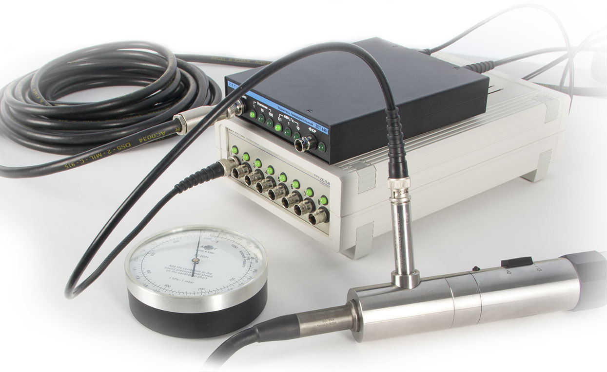
All the hydrophones manufactured by ZETLAB Company undergo obligatory calibration with the use of Brüel & Kjær Hydrophone Calibrator (Type 4229).

Order form - If you want to place an order or to make a request regarding technical specifications of particular product, fill out the form below:

Data protection notification

Please note that the personal data provided by you is used exclusively for the purposes of fulfilling our contractual obligations, including, but not limited to: issuing invoices, delivery documents, documentation relating to customs clearance process, etc. We do not provide your personal data to any third party except for the purposes relating to our direct contractual obligations. Upon completion of order processing and expiry of the warranty period for the Products provided by our Company, we do not store or process any of your personal data. Please note, that our Company’s Confidential policy does not imply any advertising or marketing activities with the use of your personal data (including your Company name, address, your E-mail, phone number and other information provided by you with a view to placing an Order and organization of the Delivery).