Settings of RF603 laser displacement sensors
in Z E T L A B system
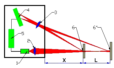
RF603 laser displacement sensors are represented by a wide range of products. The difference is the basic distance (X mm) and the measuring range (L mm) parameters.
Basic distance is the minimum distance from the bottom section of the sensor to the controlled object’s surface.
Measuring range is the distance within which the sensor performs measurements.

Figure 1. RF603 laser displacement sensor: operation schematics
In order to connect RF603 laser displacement sensor to ZET017 FFT spectrum analyzer, one can use the modified cable which is included into delivery scope of the sensor.
For the purpose of further processing of the data received from RF603 laser displacement sensor it is necessary to set the measuring channel in “Device manager” program – i.e. to set channel’s name, conversion ratio and constant component displacement value.
Channel’s name should be selected depending on sensor’s name or a particular task being solved.
Measurements unit — «mm».
Conversion ratio is to be set in accordance with the sensor’s measuring range. RF603 laser displacement sensor output analog interface has the range of 0-10 V, which corresponds to the measuring range in the following way: 0 V corresponds to minimal distance to the sensor and 10 V – to the maximal distance. Thus, in order to obtain the required ratio, it is necessary to divide analog interface maximum voltage value by the sensor’s measurement range. To our mutual convenience, ZET017 FFT spectrum analyzer has ±10 V analog interface.
![]()
The value obtained is then to be set and saved in the measuring channel settings. If the measurements environment implies that the minimal measured displacement value should correspond to the maximal distance to the sensor (or vice versa), the conversion ratio should be negative. This actually means that the conversion ratio modulus determines the displacement measuring direction. Constant component displacement value should be set as “0”.
As the conversion ratio is set, it is necessary to set the sensor on the controlled object and to send the laser beam on the displaced object, so that:
- laser beam is aimed at the controlled object
- laser beam is reflected from the controlled object, i.e. it can be detected by the sensor
- controlled object’s displacement range is within the measuring range of the sensor
Sensor’s readings can be verified by means of “DC Voltmeter” or “Multichannel oscillograph” program. If the programs depict value close to “0” value, the possible reasons for that are as follows:
- laser beam is not aimed at the controlled object, or it is focused at some other object outside of the measuring range.
- laser beam is not reflected, or it is dissipated. Otherwise it is possible that there is some obstacle between the reflected beam and the sensor.
- the controlled object is outside of the the sensor’s measuring range.
Upon completion of sensor’s mounting and check of measurements it is necessary to set back the controlled object (which has been exposed to laser beam impact) to the initial position or some other position that will be considered to be “zero position”. Then, using the “DC Voltmeter” or “Multichannel oscillograph ” software, one should change sensor’s readings in zero position of the controlled object and set this value in the section “Constant component displacement” of the measuring channel’s settings tab. As the “Apply” key is activated, “DC voltmeter” and “Multichannel oscillograph” will depict readings that are close to zero value. Now RF603 laser displacement sensor is ready for measurements performance.
During measurements performance it is not allowed to dismount or move RF603 laser displacement sensor. In the case if the sensor’s position has been changed or there occurred some changes in the controlled object, it is necessary to check the measurements range of the sensor and to reset it to zero again.
