Rail gauge control system
based on satellite navigation system GLONASS and inertial measurements by ZETLAB
Satellite navigation systems undergo drastic development and are sure to have wide application range in the future. Enhanced precision of movement parameters control and precise localization of the object represent the key factors of satellite navigation development. Efficiency of such systems is further increased in the case if they are integrated into various measurement processes.
Among major application spheres of satellite navigation one should mention satellite vehicle control, which is represented by a system for moving objects control based on satellite navigation, instruments and technologies of cellular communication and digital maps. Vehicle satellite monitoring is used for addressing logistics tasks in transportation control systems and automated lorry fleet control.
Operating principle is based on control and analysis of vehicle’s dimensional and time coordinates. On the vehicle there is installed a portable module consisting of the following parts: satellite signal receiver, modules for coordinates data storage and transfer. The data received is analyzed and sent to operator in text form along with cartographic data. The portable module should be based on satellite signals receivers operating in accordance with GLONASS standards.
However, the satellite signals received by means of the portable module do not allow to control processes related to minor (within 10 cm) displacement of the controlled object. Besides, when the controlled object moves for considerable distance, it is often necessary to define some dynamic characteristics related to the speed of movement. In this case one should use inertial measurements allowing to promptly obtain information independently of the external data sources. One of the most widely used inertial measuring instruments is represented by accelerometers.
Accelerometer is a device which measures constant component of object’s acceleration. Modern accelerometers allow to measure acceleration in three planes. The accelerometer can be used for measurement of absolute linear acceleration projection as well as for measuring of indirect gravitational acceleration projection. This very feature is used for development of tilt meters. In this particular system accelerometers BC 201 are used. They are capacitive accelerometers that can be used as linear acceleration and displacement sensors that measure both alternating and constant component of the acceleration signal. ВС 201 accelerometer perfectly suits for high-precision inertial measurements. When used together with ADC conversion module ZET 220 (equipped with active aerial and GLONASS receiver), sensor BC 201 forms a compact system with a large range of functions. Possibility of connecting ZET 220 module to PC (laptop) for further data exchange as well as offline mode operation of ADC board with signals recording to the integrated memory and power supply from batteries module contribute to universal features of the system.
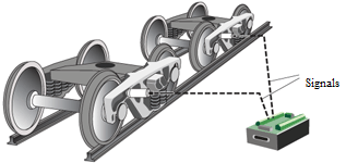
In order to detect rail gauge variations and their non-conformance to the applicable norms, one can use a system consisting of one or more ADC converters ZET 220, equipped with GLONASS receiver and two or more accelerometers. Sensors BC 201 are mounted on the truck (one sensor per each truck) in horizontal direction in transverse axis to the direction of train’s movement. Then the sensors are connected to corresponding modules ZET 220. To establish communication with GLONASS network, aerials are mounted at the surface of train sections (the aerials are further connected to corresponding modules of ZET 220).
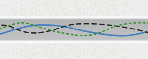
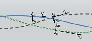
The essence of the method for rail gauge control is based on measuring transverse acceleration of the moving truck. Since the rail gauge is variable for a number of reasons, each truck has a degree of freedom in transverse direction, and, hence, its own trajectory. The figure below (to the left) shows several variants of movement along the rails. Each figure shows movement along an uneven rail section with large bend radius value (see the figure below – to the right). This causes centripetal accelerations calculated in accordance with the formula:
a=v2/r
whereas v — speed, r — bend radius value.
When the train is moving along bended sections of the railway, each train section is displaced along sraigth trajectry by a certain value. Since this value is not constant at each moment of time, it causes acceleration in transverse direction – this acceleration is measured by accelerometers.
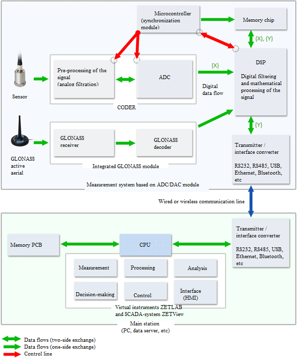
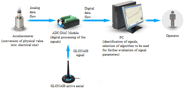
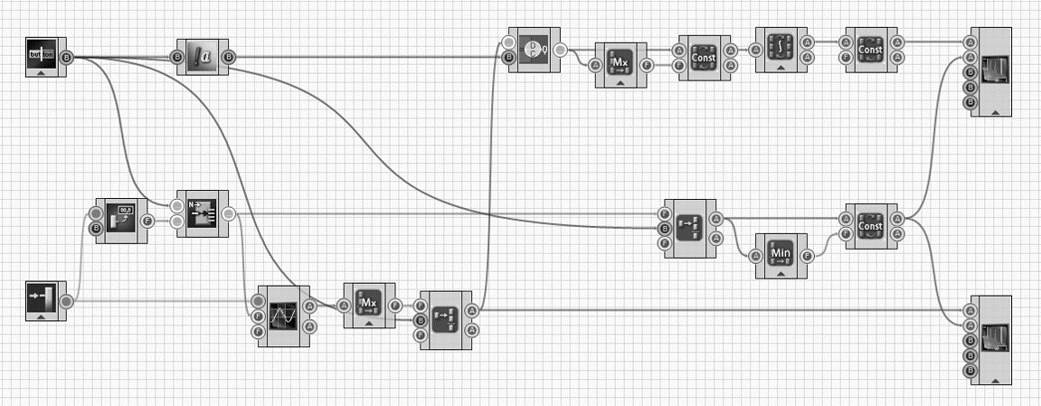
The measured analog signal is digitized by means of ZET 220 module, operating principle of which is based on analog-to-digital conversion. Information in digital form is further transfered to PC for further processing. Post-processing of the signals obtained is performed by means of mathematical tool: after having calculated the source acceleration signal integral we will get the speed of train section movement in transverse direction. After having integrated the source signal twice we will find the value of relative movement of the train section to the left and to the right. Simultaneously with analog signal processing there is performed receiving of data from GLONASS system for the purpose of obtaining such parameters as coordinates and speed of the train. Operating principle of the monitoring process is specified in the figure below:
As the basis of rail gauge uneveness control there is used the value of relative movement of train section to the left and to the right. Since the sensors are fixed in transverse direction to the way of the train, it means that the accelerometers will be detecting centrifugal acceleration in the areas where the railway section has a bending. That is why there are two or more sensors used in the system for the performance of differential measurements.
Thus, there are two accelerometers in the system. Since the sensors have identical measuring parameters, it means that all the impacts on the train section caused by the train movement will be detected in identical way, but with a certain time delay. This delay is equal to the time required for the train to pass the distance between the two sensors. Thus, knowing the distance between accelerometer and the speed of the train (obtained from GLONASS system), it is possible to calculate the delay time. Then the signals obtained are synchronized (a delay is set to one of the signals based on the value obtained) and extracted from each other. The differential signal obtained undergoes double integration, and thus, the value of train sections deviation in the course of movement is obtained.
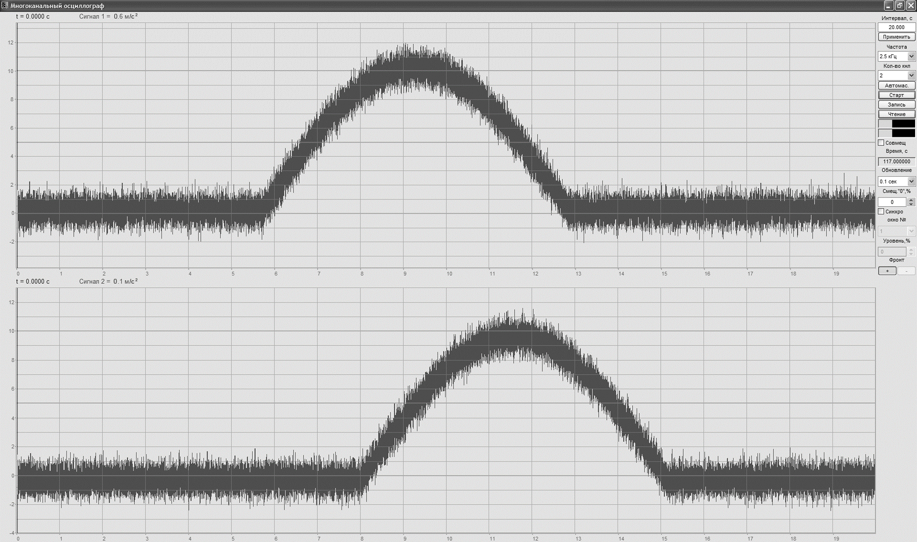
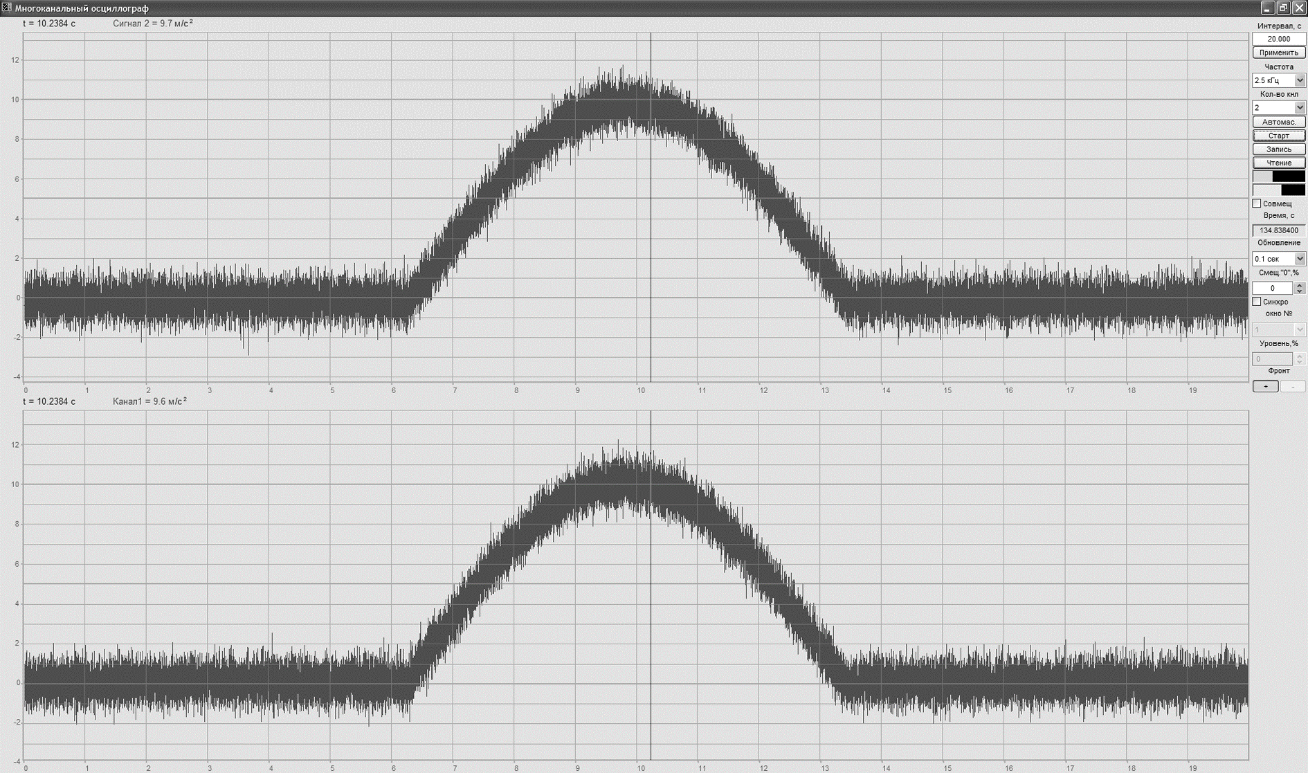
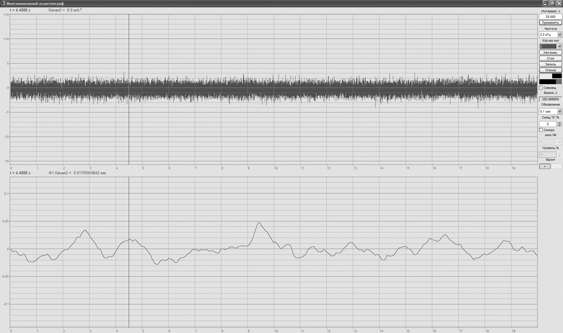
The figure shows dependence of acceleration signals received from the two sensors on time. One can clearly see that the signal’s acceleration maximum value of the first sensors occured in 9-th second and that of the second sensor – in 12-th second. At the distance between the two sensors of 100 meters and train speed of 120 km/h, we should set the delay of the first signal for 3 seconds (see the central figure). Then we perform extraction of the signals from each other and double integer the value (see the figure in the right). As a result we have a graph of relative uneveness of two train sections movement along the railway. By means of detailed analysis the operator can estimate rail gauge of a particular railway section.
Since zero signal level of movement trajectory relative uneveness corresponds to identical movement of both train sections, the measured value of signal’s alternating component may be used for estimation of rail gauge parameter at each point of the railway. Large value of this signal parameter stands for wide rail gauge and vice versa.
As for practical use of the system, it can be represented in the following way: “measurent and instant display of the result”:
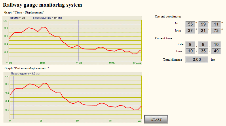
Monitoring system operation results are represented by means of SCADA-system ZETVIEW (see the figures below). Use of SCADA system allows the user to amend measurement and control process logics, change its outlook and, if necessary, set the system in accordance with personal preferences.
From operator’s point of view, the system is represented by graphs of train sections movement relative uneveness in transverse axis, current time and the distance. In this case it is always possible for the operator to find the exact section of the railway at which rail gauge deviation from the required range is detected. The graphs are formed based on GLONASS system data, time and coordinates of moving object, which are represented as a distance.
In order to make a clear view of the controlled route, it is possible to perform several measurements in the course of train movement (in both directions). The accumulated statistics provides a clear notion of the railway state.
Increased amount of the measuring sensors contributes to enhanced precision of system operation, since it allows to analyze data from several pairs of accelerometers simultaneously.
Among system advantages one should mention its cost-effective and efficient implementation: each train section is equipped with measuring instruments, which enables constant monitoring of the entire railway network. Simplicity of system operation and maintenance allows to use it not only for railroad networks, but also for other types of transport facilities.
Additional advantage of the system is the graphical representation of the measurement process. The graphs clearly display non-conformance of the rail gauge to the set requirements, thus allowing to perform prompt localization and elimination of the defects found.
The article has been published in the magazine “Knowledge-intensive technologies” № 10, 2010
Authors: Antonov A., Krasovskiy A.
References cited:
C. J. Savant “Principles of inertial navigation”;
O. A. Stepanov “Integrated inertial satellite navigation systems”.


