Power Quality Control
The 4/8-channel system is designed for measuring and controlling the quality of electric power.
The system connects to a personal computer via USB 2.0, Ethernet, or Wi-Fi. The software supplied with ZET 017-E4/8 allows to measure the following parameters:
- voltage (phase, line);
- current (phase);
- phase angle between current and voltage;
- power (active, reactive, full by phases, and total);
- energy (active, reactive, full by phases, and total);
- power factor per phase (PF);
- cosine attributed to the fundamental harmonics (cos (fi));
- frequency of the measured voltage;
- levels of harmonics (residual and full harmonic content for each harmonic phase and current);
- distortion factors of harmonicity and harmonic constituents of current;
- phase angle between harmonics of current and voltage;
- maximum/minimum values of phase voltage, current, active, reactive and full power.
ZET 017-E4/8 system is included into the State Register of Measuring Instruments.
The system has a mode of operation as a standalone digital recorder with the possibility of subsequent reproduction and analysis of the recorded signals. Quality-to-price ratio of this system makes it truly unique if compared to similar devices currently available on the market.
The system includes:
- measuring module ZET 017-E4/8 based on ZET 017-T4/8 station;
- personal computer;
- current and voltage sensors;
- ZETLAB software;
- all necessary cables, adapters, and accessories.
Main Specifications:
| Power supply voltage | ~ 220 V, + 12 V |
| Measured voltage range | 0 to 1,000 V |
| Measured current range | 0.01 to 100 А |
| Connection type | 1, 2, 3 phases (with or without zero line) |
| Current and voltage harmonics measurement | up to 100 |
Applicable international standards (Highlights):
Scope
The standard in question outlines performance and quality regulations for power (PQ) in electric networks of general purpose power supply systems with three-phase and single-phase alternating current at 50 Hz frequency at the points of connection of electric networks owned by various power consumers, or receivers of electric energy (general connection points).
PQ requirements established by this standard represent the levels of electromagnetic compatibility for conductive electromagnetic interference within general purpose power supply systems. Compliance with the mentioned regulations ensures electromagnetic compatibility of electric networks of general purpose power supply systems and electric networks of power consumers (receivers of electric energy).
The norms established by this standard are applied for designing and operating the electric networks, as well as for establishing the levels of interference immunity of electric energy receivers and the levels of conductive EMI introduced by these receivers.
Definitions, Designations, and Abbreviations
Terms used in this standard:
– general purpose power supply system is a set of electrical plants and electrical devices of the power supply organization, which are designed for supplying power to various consumers (receivers of electric energy);
– general purpose electric network is a power network of the power supply organization, which is designed for transmitting electric power to various consumers users (receivers of electric energy);
– power center is a low voltage switchgear of the power plant or a secondary voltage switchgear of the stepdown substation within the power grid, to which the distribution networks of the relevant region are connected;
– general connection point is a point of the general purpose electric network, which is electrically closest to networks of the relevant power consumer (input devices of the relevant electric energy receiver), and to which the electric networks of other consumers (input devices of other receivers) are connected or can be connected;
– power consumer is a legal entity or an individual using the electric energy (power);
– conductive electromagnetic interference in power supply system is an electromagnetic interference spreading across the elements of the electric network;
– level of electromagnetic compatibility in the power supply system is a regulated level of conductive electromagnetic interference, which is used as a reference for coordination between the permissible level of interference introduced by technical facilities of the power supply organization and power consumers, and the interference level accepted by technical facilities without interruption of their normal operation;
– r.m.s. voltage shape is a step time function formed by the root-mean-square values of voltage, which are discretely defined in each voltage half-cycle at fundamental frequency;
– flicker is a subjective human perception of oscillations of luminous flux of artificial light sources, which are caused by voltage fluctuations in the electric network that powers these sources;
– flicker dose is a degree of human susceptibility to flicker over a set period of time;
– flicker perception time is a minimum time for subjective human perception of flicker caused by voltage fluctuations in some form;
– voltage change frequency is the number of single voltage changes per time unit;
– voltage change duration is a time interval from the start of single voltage change to its final value;
– voltage failure is an abrupt decrease of voltage below 0.9 Unom at an electric network point, followed by voltage recovery to the original or approximately original level over the time span from ten milliseconds to tens of seconds;
– voltage failure duration is a time interval between the starting point of voltage failure and the point of voltage recovery to original or approximately original level;
– relative frequency of voltage failures is the number of voltage failures of certain depth and duration over certain time against the total number of failures for the same period of time;
– voltage pulse is an abrupt change of voltage at an electric network point, followed by voltage recovery to the original or approximately original level over the time span of up to a few seconds;
– pulse amplitude is the maximum instantaneous value of voltage pulse;
– pulse duration is a time interval between the starting point of pulse and the point of recovery of instantaneous value of voltage to original or approximately original level;
– temporary overvoltage is voltage increase above 1.1 Unom at an electric network point lasting more than 10 ms, which occurs in power supply systems due to switching or short circuits;
– temporary overvoltage coefficient is a value equal to the ratio between the maximum value of the amplitude voltage envelope over the time of temporary overvoltage to the amplitude of nominal network voltage;
– temporary overvoltage duration is a time interval between the start and end of temporary overvoltage.
Power Quality Indicators
The PQ indicators include:
- steady-state voltage deviation;
- voltage change range;
- flicker dose;
- distortion factor of sine curve of voltage;
- coefficient of N harmonic constituent of voltage;
- negative-sequence voltage unbalance factor;
- zero-sequence voltage unbalance factor;
- frequency deviation;
- voltage failure duration;
- pulse voltage;
- temporary overvoltage coefficient.
When determining the values of certain PQ indicators, the following auxiliary parameters of electric energy are used:
- voltage change frequency;
- interval between voltage changes;
- voltage failure depth;
- voltage failure frequency;
- pulse duration by 0.5 of its amplitude;
- temporary overvoltage duration.
PQ Norms
- voltage deviation;
- voltage fluctuations;
- voltage unsinusoidality;
- voltage unbalance;
- frequency deviation;
- voltage failure;
- voltage pulse;
- temporary overvoltage.
Power Properties, Indicators, and the Most Likely Reasons of PQ Deterioration
| Power Properties | PQ Indicator | Most Likely Originators of PQ Deterioration |
| Voltage deviation (Figure 1) | Steady-state voltage deviation | Power supply organization |
| Voltage fluctuations (Figure 1) | Voltage change range Flicker dose |
Consumer with alternating load |
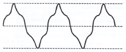
| Voltage unsinusoidality (Figure 2) | Voltage waveform distortion factor Coefficient of N harmonic constituent of voltage |
Consumer with non-linear load |
| Three-phase voltage system unbalance | Negative-sequence voltage unbalance factor Zero-sequence voltage unbalance factor |
Consumer with unbalanced load |
| Frequency deviation | Frequency deviation | Power supply organization |
| Voltage failure (Figure 1) | Voltage failure duration | Power supply organization |
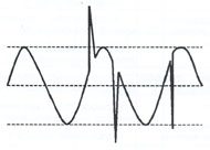
| Voltage pulse (Figure 3) | Pulse voltage | Power supply organization |
| Temporary overvoltage (Figure 1) | Temporary overvoltage coefficient | Power supply organization |

Figure 1


