LVDT-displacement sensors
Abbreviation “LVDT” stands for “Linear Variable Differential Transformer “.
LVDT-displacement sensors are electro-mechanical transducers transforming linear displacement of the object (to which they are mechanically connected) into electrical signal. One of the distinctive features of the sensors in question is that they have a wide displacement measurement range (from several dozens of microns up to ±0,5 m) and are suitable for using in severe operating conditions. The first advantage comes from LVDT-displacement sensors operating principle and the other one – from their structure.
There are a lot of pulse displacement sensors, operating principle of which is based on registering the moment when the controlled object crosses certain mark (registering of this event is performed by means of magnetic or optron sensors). Registering of the corresponding event leads to the formation of an impulse at sensor’s output. It is understandable that such sensors have limited dynamic displacement measurements range as well as high error probability in velocity and acceleration measurements (since these values are derivatives from the displacement value) – these features sometimes are inacceptable. The LVDT-displacement sensors that are described in the present article do not have these drawbacks since their signal is constant.
LVDT-displacement sensors: operating principles
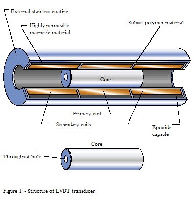
Figure 1 shows LVDT-displacement sensor schematic structure. The basic components of the system are one primary and two secondary wirings (the wirings are normally mounted on a stationary shaft) and a moving core shaft. Primary wiring is located symmetrically between two identical secondary wirings. The coils are mounted on thermal-proof reinforced polimeric material within a leak-proof casing used for protection from moist and hostile environment impact. Moving core shaft is made of highly-permeable magnetic material, it has cylindrical shape. The core shaft moves inside of sensor’s inner cavity.

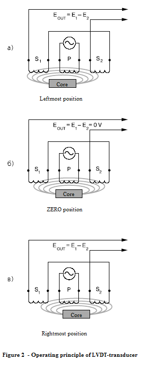
Primary wiring power supply is performed by means of alternating sine voltage (typical value: 3V, 3kHz). Sensor output signal is the voltage value difference of the two secondary wirings u8212 – i.e. the differential voltage. The alternating differential voltage is normally transmitted into constant current signal by means of electronic module.
Figure 2 shows LVDT-displacement sensor operating principle. If the moving core shaft is located in the middle of the sensor (in the so called “zero position”), then the magnetic field P, produced by the primary wiring, is symmetrical. This actually means that the magnetic fields passing through secondary wirings S1 and S2 are equal, hence, the EMF values E1 and E2, produced by the wirings, are equal as well, i.e. the differential voltage is equal to zero as well. Shaft core displacement from zero position causes distortion of magnetic field (i.e. one of the secondary wirings has larger magnetic flow then the other – see Figure 2). Hence, EMF values (which are proportional to magnetic field power), differ as well.
Figure 3a shows the differential output voltage amplitude (EOUT) change depending on the position of the core shaft. Maximum EOUT value is normally several Volts. EOUT phase angle in relation to primary voltage remains unchanged up to zero position, after which the phase angle is normally changed by 180 degrees (see Figure 3b). Phase angle can be used to determine displacement direction from the zero position during alternating current signal conversion by elecrical module. Then the output signal will have structure similar to that shown in the Figure 3c.
LVDT-displacement sensor operating principle and structure have a number of advantages.
 Absence of motion parts — is one of the key LVDT-sensor advantages. In normal operation mode there is no mechanical contact between core shaft and the coils. This feature is especially important for small displacement measurements – for instance, for vibration control.
High sensitivity: absence of motion parts and physical operation principle enable control of minor core shaft displacements along with good measurements results repeatability. Minimal measuring value is limited by initiator noise level and resolution.
Ultimate mechanical wear resistance – is attributed to the absence of moving parts. Hence, there are no factors between core shaft and the coils that would negatively affect mechanical wear resistance factor. This leads to high reliability parameter which is especially important for aerospace and nuclear industry as well as for other spheres, where reliability is considered to be the key factor.
Runout protection. Inner opening of most LVDT-displacement sensors is open from both sides, which means that in the case of “overshoot” (i.e. controlled object and core shaft displacement beyond the specified limits) there will be no mechanical damage of the sensor – the core shaft will simply come out from the sensor without damaging it. This type of protection is especially good for strain gauges and extensometers (An extensometer is a device that is used to measure changes in the length of an object), which are used for material extension measurements.
Single direction of sensitivity. LVDT-displacement sensor reacts to core shaft displacement only in single direction and does not have any response to displacement in other directions. This feature is especially important in applications where there is a slight fluctuation during core shaft displacement.
Separation of coils and core shaft. The coils are mechanically separated from the moving core shaft and the coils are placed inside of leak-proof casing, which is important for use of the LVDT-displacement sensors in hydraulic and servohydraulic drives.
Resistance to environmental impact. LVDT-displacement sensors materials and design enable anti-corrosion properties and wear resistance, which makes LVDT-displacement sensors resistant to environmental impact. The coils are covered with epoxide resin which makes them resistant to moisture, single shocks and vibration impact. Inner screen is made of magnetically permeable material which allows to minimize electromagnetic field impact. Both the core and the core shaft are made of corrosion-resistant materials also having magnetic insulation properties. For the purpose of using the sensor in explosion- and fire-hazard areas as well in aggressive environments, the sensor can also be protected from environmental impact by means of being welded into a “package”. LVDT-displacement sensors normally have wide operational temperature range and can be used in cryogenic technologies, at high temperature and radiation levels (for instance, in the fission reactor).
Zero point repeatability. Zero point position is extremely stable and repeatabe even at extremely high temperatures.
Good dynamic properties. Absense of motion parts enables fast response of LVDT-displacement sensor’s core. The dynamic response is limited only by the core weight value.
Reference: “Electronic components” #11 2006
