
General Specifications Of Resistive Strain Sensors
There is a wide range of resistive strain sensors for optimal solution of the set tasks. Each resistive strain sensor has precision resistive foil grids, which are mounted on a bed of organic material.
Each series of resistive strain sensors is unique, having its own design, construction features, and a specific combination of alloy and bed material. The descriptions of resistive strain sensors contain details on dimensions, operational characteristics, and application notes, as well as information of the alloy and bed material.
Main Specifications of Resistive Strain Sensors
| Series | EA | EP | |
| Application | Foil constantan combined with durable, pliable polyimide bed. Wide selection of available options. Originally designed for general static and dynamic analysis of strain. Not recommended for high-frequency transducers |
Special annealed constantan alloy with durable, highly elastic polyimide bed. Mainly used for measuring large strains. Available with options E, L, and LE (may limit the extensibility parameters) |
|
| Temperature range, °С | Operating: -75 to 175 Short-term: -195 to 205 |
−75 to 205 | |
| Measuring range (the range of elastic strain against grid length), % | ± 3% for sensors with up to 3.2 mm measuring grid ± 5% for sensors with at least 3.2 mm measuring grid |
± 10% for sensors with up to 3.2 mm measuring grid ± 20% for sensors with at least 3.2 mm measuring grid |
|
| Strain level, µm/m | ±1,800 | ±1,000 | EP series sensors demonstrate zero offset during highly cyclic strains |
| ±1,500 | |||
| ±1,200 | |||
| Number of cycles | 105 | 104 | |
| 106 | |||
| 108 | |||
Strain and Temperature Range
The permissible strain range is defined with indication of the recommended operating temperature for various applications. Cyclic strain level charts, depending on the number of cycles, are specified for all series and show the overall norm for nominal fatigue performance. As fatigue performance of resistive strain sensors depends on various conditions, the relevant instructions shall be learned.
The below fatigue strength curves of strain sensors match the reversible strain levels. They can also apply to unidirectional strain subject to amplitude peaks reduction by 10%. For instance, the fully reversible strain range of ± 1,500 µm/m is approximately equal to the fatigue damage of resistive strain sensor with strain levels:
- 0 to + 2,700 µm/m,
- 0 to – 2,700 µm/m,
- – 200 to + 2,500 µm/m.
However, the average strain value increased in the direction of stretching during the cycle leads to earlier breakdown. It should be noted that all the operational characteristics of resistive strain sensors are nominal, because behavior of an individual sensor may change during installation or under the environmental conditions. In addition, these parameters apply to resistive strain sensors without accessories, having active length of 3 mm or more, unless otherwise specified.
EA Series
EA series resistive strain sensors made of constantan are widely used for general purpose experimental analysis of stress. A basic model has an open design with 0.025 mm durable elastic bed of cast polyimide. This series offers a wide range of models and is usually cheaper. This series has many optional features, such as different shape of lead bonding cover and protective encapsulation. The bed is prepared for solid fixation by all standard glues for resistive strain sensors. The range of elastic strain against the the grid length for resistive strain sensors with at least 3 mm grid: ± 5%; for sensors with shorter grid: 3%.
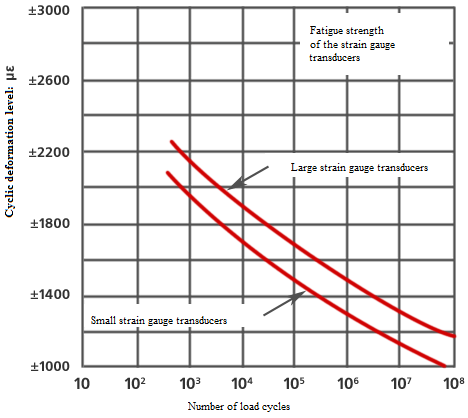
Fatigue strength of EA series resistive strain sensors
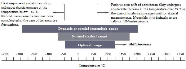
Operating temperature range of EA series resistive strain sensors
EP Series
EP series resistive strain sensors are specifically designed for large strain measurements, > 3-5%. A basic model has an open design with 0.025 mm durable elastic bed of highly elastic cast polyimide. Measuring grid is made of the special grade annealed constantan foil for maximum plasticity. The series offers 08 and 40 compensation for application on metals and plastic, respectively. The precise values of temperature self-compensation are typically irrelevant for operation in plastic state, because the temperature error is very small compared to the measured high levels of strain. The strain limit for EP series resistive strain sensors with at least 3 mm grid: ± 20%; for sensors with shorter grid: 10%. The optional designs mainly reduce the extensibility. EP series resistive strain sensors can be purchased by special order with all options available for EA series.
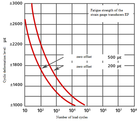
Fatigue strength of EP series resistive strain sensors
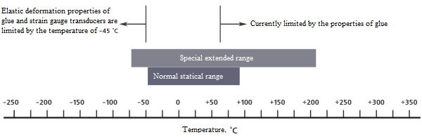
Operating temperature of EP series resistive strain sensors
Dimensions of Resistive Strain Sensors
Measuring grid length is an important parameter for selection of a resistive strain sensor, and usually it becomes a decisive factor. The dimensions specified for length and width refer to the active size of measuring grid. The overall length and width of a resistive strain sensor refer to actual size along the grid edges, not including the alignment marks or bed. The bed dimensions are nominal with up to ± 0.4 mm tolerable deviation. If the sensors are encapsulated, the bed can be downsized, but no more than by 0.25 mm to the edge of grid pattern, with no loss of sensor performance quality. For these purposes, the majority of models also include trim marks for use in confined spaces.
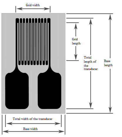
Designations of dimension parameters
Self-Temperature-Compensation (S-T-C)
All resistive strain sensors with “XX” in third part of sensor designation code (for example, MT-EA-XX-0.38DJ-120) have self-temperature-compensation for application on structures made of materials with a certain thermal expansion coefficient.
When selecting a resistive strain sensor, replace the XX code part with the desired S-T-C number, which represents the thermal expansion coefficient of the construction material. The table of resistive strain sensor labels contains the available S-T-C numbers for grid alloys. The 06 and 13 values available for alloy A are typical for general-purpose resistive strain sensors. If there are no special requirements, the 06 value is the most suitable.
| S-T-C Number | Linear Expansion Coefficient of Material | Material |
| 00 | 1.4 | Invar alloy (FeNi) |
| 0.5 | Quartz, molten | |
| 1.4 | Titanium silicate* | |
| 03 | 5.4 | Burnt alumina (aluminum) |
| 4.9 | Molybdenum* | |
| 4.3 | Tungsten | |
| 5.6 | Zirconium | |
| 05 | 9.2 | Silicate glass |
| 9.9 | Ferritic stainless steel | |
| 8.6 | Titanium, pure | |
| 8.8 | Titanium alloy, 6 AL-4V* | |
| 06 | 11.5 | Beryllium |
| 10.8 | Gray cast iron | |
| 12.6 | Inconel, Ni-Ct-Fe alloy | |
| 12.1 | Inconel X, Ni-Cr-Fe alloy | |
| 13.5 | Monel, Ni-Cu alloy | |
| 11.9 | Nickel, Cu-Zn-Ni alloy | |
| 11.3 | 4340 steel | |
| 12.1 | Carbon steel, 1008, 1018* | |
| 10.8 | Stainless steel, hardened- | |
| 10.3 | Stainless steel, hardened- | |
| 9.0 | Stainless steel, hardened- | |
| 09 | 16.7 | Beryllium-copper, Cu25, BE25 |
| 18.4 | Phosphor-bronze, Cu90, Sn10 | |
| 16.6 | Copper; 99.9%+ | |
| 17.3 | Austenitic stainless steel | |
| 17.4 | Austenitic stainless steel | |
| 16.0 | Stainless steel | |
| 13 | 23.2 | Aluminum alloy 2024-T4* |
| 20.0 | 7075 T6; brass | |
| 22.7 | Cu70 Zn30; pure tin | |
| 15 | 26.1 | Magnesium alloy, AZ-318* |
| 18, 30, 40 | Plastics and composites |
* the material used for determining the thermal output signal