Eddy probe systems
Eddy probe systems (eddy current sensors) are used for non-contact displacement vibration and rotary frequency measurements of conducting objects.
Such systems are used for diagnostics of industrial turbines, compressors and electric motors. In most cases the measured parameters are represented by axial displacement and radial vibration of rotor shaft.
Eddy probe systems (also referred to as proximity sensor system) consist of non-contact eddy probe, extension cable and a driver. Eddy probe is a steel shaft with dielectric pin (with inductive coil inside) at one end and of coaxial cable section at the other. Coaxial extension cable (max. length – 0,5 m) enables connection to the driver.
The driver is represented by electronic unit emitting excitation signals of the prober and information-bearing parameter. Driver’s output signal is an electrical signal that is proportional to the distance between eddy probe end and the controlled object.
Eddy probe systems: operating principles
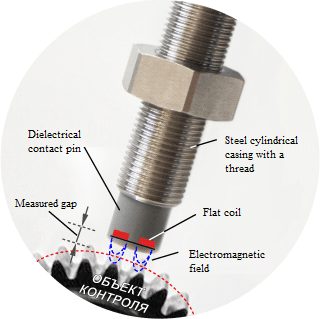
Eddy probe dielectric pin has an inductance coil inside (Figure 1)

Figure 1
The driver causes elctromagnetic oscillations inside of the coil. Thus, there is formed an electromagnetic field coming into interaction with the controlled object’s material. In the case if the material has conductive properties, eddy currents are formed on its surface. The eddy currents, in their turn, affect coil parameters (i.e. its active and inductive impedance). These parameters change depending on the gap between the controlled object and probe edge. The driver converts the gap length change into electrical signal and performs its linear approximation and scaling.
Eddy probe systems: structure
Most of the eddy probe systems design variants have a probe – its structure depends on installation area and measurement range. The probe can be connected to the driver whether directly or via extension cable. For the purpose of mechanical damage prevention the connection cable is placed inside of flexible hose. The driver consists of air-tight metal box with coaxial connector for the cable, power, gnd, common wire and output signal.
Eddy probe systems: specifications
Eddy current sensors have good frequency response (i.e. reaction to the change of the distance between probe edge and controlled object). Frequency response range is 0 – 10 000 Hz. Frequency response uneveness does not exceed the level of 0,5 dB.
Eddy probe systems: input and output
Input parameter of the eddy current sensor is the gap between the probe edge and the conductive object. The measured gap value is several millimeters and it depends on the diameter of the coil placed inside of the dielectric probe. Output signal (which is proportional to the measured gap) can be represented as power, current or a digital value (information representation type is determined by particular control system type). For drivers with power output signal sensitivity ratio is specified (i.e. gap value to electrical signal conversion ratio) – in most cases the sensitivity ratio value is 8 mV/µm. Eddy current sensor conjugation with standard control systems often requires conversion of output voltage into 4-20 mA current loop of digital format. The devices that combine driver and additional conditioner functions are called transmitters.
Eddy probe systems: application spheres
Eddy current sensors major sphere of application is the control of large turbines, compressors, electric motors shafts (with splipping bearings) axial displacement and transverse beating. Even though it is also possible to use velocity and acceleration sensors for this task, it is not reasonable enough due to decline of proportional ratio between shaft and base vibration displacements at high rotation speed. The other factor is considerable (3-10 times) vibration dampening by apparatus casing. Both factors lead to high error of the results obtained. Eddy current method, to the contrary, has an exceptional precision (since it has no bottom frequency limit), does not require mathematical processing of the measurements results (due to direct correspondence of output signal to actual shaft displacement). In the case of small turbines, generators and compressors (with rolling bearings and light casing weight) it is reasonable to use velocity and acceleration bearings mounted on the apparatus casing.
Eddy probe systems: radial vibration
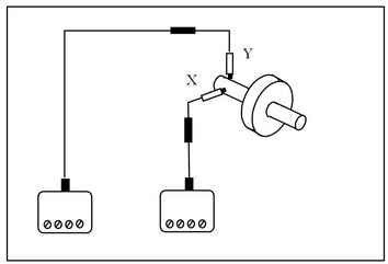
For the puprose of radial vibration measurements two sensors are usually used. The sensors are normally placed at right angles to the shaft and at 90° to each other (Figure 2).

Figure 2
X-Y orthogonal probes positioning improves diagnostics process since it enables receiving both general data and data for each particular axis. Additional control instruments also enable visual shaft trajectory representation in radial plane. Besides, vibration displacement vectors measurements in several axes allow to form shaft dynamic bending curve.
Eddy probe systems: axial displacement
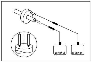
For the purpose of axial displacement measurements the sensor is placed at right angle to the shaft end plane and (or) the plane of measuring bar (Figure 3).

Figure 3
In some cases two sensors are used (i.e. main and back-up channels).
Eddy probe systems: rotation frequency
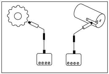
Eddy current sensors are used for shaft rotation frequency measurements (Figure 4).Sensor response is normally provided by small opening reamed in the shaft. This sensor can be used together with radial vibration X-Y sensors. In this case the sensor performs functions of phase mark conditioner. The shaft mark is used for shaft rotation trajectory control. Besides, structural elements of the shaft (for instance, gear wheels) can also be used for sensor response forming.

Figure 4
In the eddy probe system it is possible to use a transmitter instead of the driver – this will allow to receive a signal proportinal to the amount of rotation cycles per minute.
Eddy probe systems: additional features
Eddy probe systems are also used for:
- shafts misalignment measurements;
- dielectric paint coating thickness measurement on a steel surface;
- elements relative thermal extension measurements;
- parts and mechanisms wear control;
- use as inductive limit switch;
- dielectric layer metallized layer thickness measurements.
Eddy probe systems: system configuration
There are several available eddy probe systems configurations – the difference between them is probe coil diameter, cable length, output signal parameters and measured value nature. Probe coil diameter determines measurement range and interaction surface dimensions of electromagnetic field with the controlled object. Interaction surface dimensions are considered to be equal or less then probe coil double diameter. This feature is to be taken into consideration during probe mounting and shaft transverse vibration control, since in this case the exposed surface has cylindrical shape, which causes system error that grows together with coil diameter increase and shaft diameter decrease. Each particular combination of coil diameter and system cable length requires calibration of a driver or a transmitter which is to be marked accordingly. Non-compliance of system cable length or probe coil diameter to driver or transmitter marking results in error ratio growth. The Table lists basic system specifications allowing the user to determine suitable probe system configuration for addressing particular task. Basic characteristics of eddy probe systems are available in the “Products” Section.
