DATA EXCHANGE DIAGNOSTICS
in a measuring line
Data exchange diagnostics in a measuring line is performed by sending to the line ReadHoldingRegisters and/or ReadInputRegisters commands with subsequent analysis of the response or its absence. By default, the queries are sent with the maximum available frequency. The purpose of the diagnostics is to detect faults and bottlenecks in the measuring line from the data exchange point of view between the converter and a digital sensor.
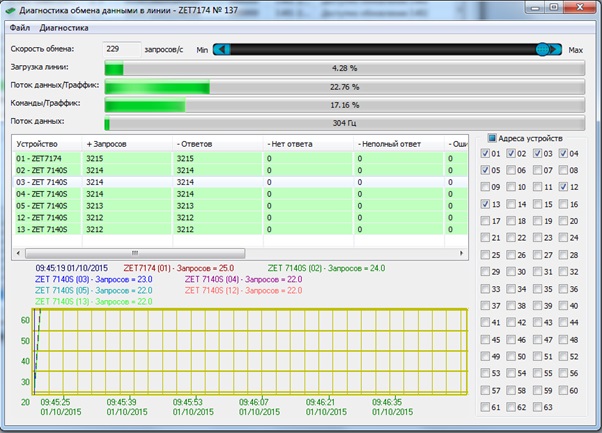
Prior to diagnostics, it is necessary to check the IDs of those interface converters for which the diagnostics of the measuring lines formed by the converters is to be performed. Go to “Service operations with ZET 7xxx”, open the “Actions” menu in the “Diagnostics” section, select “Data exchange diagnostics”. The program will start testing the measuring lines, the results will be displayed in the “Data exchange in the line diagnostics” window.

The following areas are displayed in the “Diagnostic information” window:
- Exchange rate: dispalys the current exchange rate in the digital channel between the interface converters and the digital units;
- Line Load: displays the current load of the digital line (as a percentage of the maximum capacity);
- Device List Area: displays the list of devices starting from the numbers indicating the device address in the digital line;
- Device Address Area: displays addresses to which the program sends diagnostic queries (the selected addresses are checked).
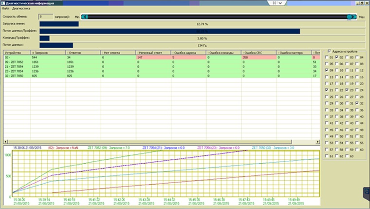
The figure below shows an example of fault diagnostics caused by address duplication (namely, address 2) assigned to the digital units.
This fault has a specific indication in the “Diagnostic information” window. When addresses of some devices in the Modbus network are the same, the devices with the same address respond simultaneously to each query which causes incorrect responses to the queries; then the values in columns “Incomplete response”, “Address error”, “Command error” and “CRC error” are incremented. Besides, the overall exchange rate drops in the line, and the value displayed in the “Exchange rate” field will be different from the value normal for this line.
Thus, if the measuring line has been built correctly, the following ratios must be valid:
For a line with ZET 7070:
- 2,400 bps ≋ 10 queries/sec
- 4,800 bps ≋ 15 queries/sec
- 9,600 bps ≋ 30 queries/sec
- 14,400 bps ≋ 40 queries/sec
- 19,200 bps ≋ 50 queries/sec
- 38,400 bps ≋ 75 queries/sec
- 57,600 bps ≋ 90 queries/sec
- 115,200 bps ≋ 110 queries/sec
For a line with ZET 7174:
- 100 kbps ≋ 175 queries/sec
- 300 kbps ≋ 210 queries/sec
- 1 Mbps ≋ 245 queries/sec
For a line with ZET 7076:
- 2,400 bps: is not supported
- 4,800 bps ≋ 10 queries/sec
- 9,600 bps ≋ 20 queries/sec
- 14,400 bps: is not supported
- 19,200 bps ≋ 30 queries/sec
- 38,400 bps ≋ 45 queries/sec
- 57,600 bps ≋ 50 queries/sec
- 115,200 bps ≋ 55 queries/sec
For a line with ZET 7176:
- 100 kbps ≋ 110 queries/sec
- 300 kbps ≋ 140 queries/sec
- 1 Mbps ≋ 180 queries/sec
In some cases, the number of queries per second may differ from the normal value, however, this number should remain stable. If no stability is observed over time, this means there may be problems in the line.
The digital sensor addresses always correlate to their measuring channels, so it should be noted that some digital sensors, for instance ZET 7152 or ZET 7154 have more than one measuring channel. In configuring digital sensors which have more than one address, only the address of its first measuring channel must be set; however, it should be noted that the following addresses in the list (depending on the number of the measuring channels within the sensor) will also be used and must not be assigned to other digital sensors to be installed within the same measuring line.
Example: A ZET 7152 digital sensor configured for address No 5 is installed to a measuring line. Since the ZET 7152 digital sensor has three measuring channels, addresses No 6 and 7 cannot be assigned to other digital sensors within this measuring line.


