Connecting Zetsensor To Third-Party RS-485 Converters
with ICP-CON i-7561 and USB-COMi-Si-M as an example
Introduction
ZETSENSOR digital sensors with RS-485 interface can be connected to third-party devices supporting the same interface.
In particular, ZETSENSOR digital sensors can be connected to PC with RS-485 interface converters via USB ports of third-party manufacturers.
The article describes connection examples of the digital strain-gauge sensor ZET 7010 to two USB ↔ RS‑485 interface converters: ICP-CON i-7561 [1] and USB-COMi-Si-M [2].
General Information
A two-wire RS-485 (half duplex) interface is used.
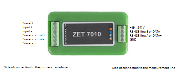
Digital ZETSENSOR device has four outputs (see Figure 1):
- +12 (9 to 24) V (orange or red);
- DATA- (blue);
- DATA+ (white-blue or green);
- GND (white-orange or yellow).
Digital sensor and converter are connected via three wires: DATA-, DATA+, and GND.
Caution
A terminator, i.e. 120 Ohm resistor is required on the line between DATA+ and DATA-.
If the line length is over 10 m, the terminators must be placed at its ends. In some converters, the terminator is already integrated into the device structure, for example, in ZET 7070.
The power of ZETSENSOR is external: +9 to + 24 V against GND.
Power supply level to converter depends on device specification. Usually converters from USB to RS-485 are powered by USB.
The converter is usually available in Windows system in form of a COM port and in Linux in form of a /dev/ttyUSB* device. To operate these converters one can use almost any application with support of Modbus RTU.
ICP-CON I-7561 Connection Layout
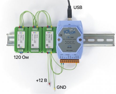
Example of ZET 7010 strain-gauge sensor connection to ICP-CON i-7651 converter is shown on Figure 2.
ICP-CON I-7561 Converter Configuration
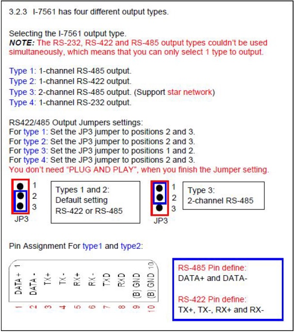
The converter must be set to RS-485 two-wire mode. To do this, open its body and set JP3 jumper to 2-3 position (Figure 3).
USB-COMI-SI-M Connection Layout
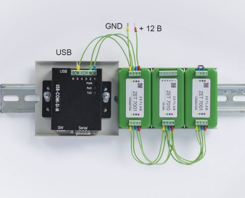
Connection example of ZET 7010 strain-gauge sensor to the USB interface converter from USB to RS-485 with optical insulation USB-COMi-SI-M is shown on Figure 4.
DB9 output or TB1 terminal block can be used. The pinout in both versions is as follows: 1 (DATA-), 2 (DATA+) and 5 (GND).
Pay attention to 120 Ohm resistor. In this example, the line length is small, hence it is enough to use a single terminator in any place is of the line.
USB-COMi-SI-M Configuration
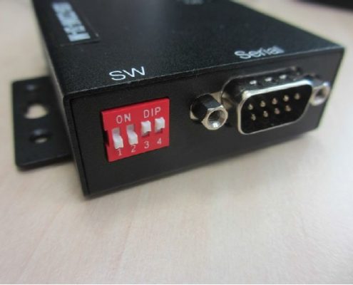
The converter must be configured to “RS-485 Half Duplex (2 wire) without Echo” mode in accordance with adjustment instructions [4]. For this, SW jumpers must be set into positions OFF, OFF, ON, ON (see Figure 5).
References:
- Description of ICP-CON i-7561 — USB to Isolated RS-485 Converter:
https://www.icpdas.com/root/product/solutions/industrial_communication/converter/i-7561.html - Description of USB-COMi-SI-M — USB to RS485 port optical isolated:
https://www.vscom.de/vscom-usb-comi-si-m.html - User manual for ICP-CON i-7561:
https://ftp.icpdas.com.tw/pub/cd/Usb_tM/NAPDOS/UsbConverter/I-756x_series/manual/7000_seriesbusconvertermanual.pdf - Adjustment instructions for USB-COMi-SI-M:
https://ftp.vscom.de/multiio/winXP/info/USB-COMi-SI-M_setting.pdf

