
CONTROL SYSTEM FOR A SERVOHYDRAULIC BENCH IN A CLOSED CIRCUIT
A control system for a servohydraulic bench in a closed circuit is built based on the ZETSENSOR digital devices with CAN interface. This system features high-speed work, high accuracy, and portability. The system makes it possible to control the servomotor in automated mode using a preset profile for such parameters as pressure (force), travel, with simultaneous control of other system parameters: temperature, pressure, filter clogging, oil pressure in the the hydroelectric power station, etc.
Purpose of the control system for a servohydraulic bench in a closed circuit
The system in the above described basic configuration enables the following functions:
- automated test control using a pressure profile with travel limitation;
- automated test control using a travel profile with pressure limitation;
- manual control with the start position;
- parameter indication on the bench;
- visualization and registration of test parameters and test results to a PC.
Additionally, the system may be equipped with sensors of temperature, level, pressure in liquid mediums, and other sensors, the signals of which will be used for controlling the bench, for example, temperature block. When several benches are connected to a single hydroelectric power station, a multi-channel bench control system is created with a message exchange function between the hydroelectric power station and servo-valve control units, for correct bench disconnection.
Operating principle of the control system for a servohydraulic bench in a closed circuit
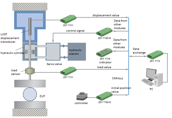
The travel sensor and force sensor are installed directly on the moving part of the bench and transmit signals proportionate to the relative piston travel and the force created by the bench on the tested object. Those signals are processed by ZET 7111 measuring units which transmit the measured values to all connected devices and display those on the ZET 7178 indicator.
The initial position of the test press is determined manually by the operator using a special controller which is connected to the ZET 7160-E encoder which transmits the set position of the controller. The ZET 7190-R control unit listening to the CAN bus controls the servo-valve in accordance with the signal from the encoder. Liquid is fed to the upper or the lower part of the hydraulic cylinder of a servo valve ensuring the piston travel and the test press control. Thus, the initial stress is created on the tested object.
Then, the automatic adjustment program is launched and the ZET 7190‑R unit performs control of the servo valve implementing the set test profile.
Control system for a servohydraulic bench in a closed circuit
The ZET 7190‑R unit ensures proportionate integral and differential (PID) control of the servo-valve according to the feedback signals from the travel and force sensors. In the unit, the parameters of the signal to the servo motor are calculated based on the sensor indications and the set test profile.
Composition of the control system for a servohydraulic bench in a closed circuit
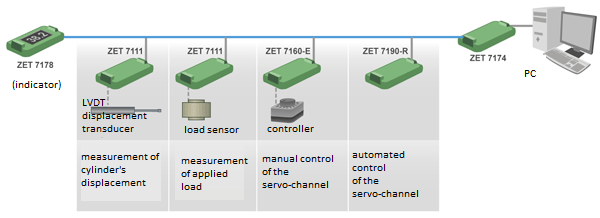
Generally, the control system for servohydraulic bench in a closed circuit consists of the following devices (see the Figure below):
- smart travel sensor; LVDT sensor + ZET 7111-L measuring unit;
- smart strain gauge: force sensor + ZET 7111 measuring unit;
- start position manual control device: controller + ZET 7160-E encoder;
- device for servo-valve automated control by a set profile: ZET 7190-R control unit;
- indicator for parameter display on the bench: ZET 7178;
- operator’s workplace: ZET 7174 interface unit + PC.
Control system for a servohydraulic bench in a closed circuit
based on the ZETSENSOR smart sensors
Application scope
The servo hydraulic bench is intended for imitating the operational load of the studied object which is installed between a fixed support and the test press. Press is controlled by the servo motor using a servo valve connected with the hydroelectric power station. Having received a control signal, the servo valve directs the liquid flow to the upper or the lower part of the hydraulic cylinder, thus ensuring the piston travel and a corresponding movement of the test press. This way, a load is created on the tested object, which may alter with time by various laws: sine, fade-in and fade-out, set level maintenance, small-amplitude oscillations, short-time force changes, etc.
A distinguishing feature of the servohydraulic benches is their dynamism, absence of a dormant state since the hydraulic cylinder, servo-valve, and the hydroelectric power station are continuously connected with each other. Thus, a potentially unstable system is created and the continuous control of the servo-valve state is required. This is why the offered control system is implemented on the CAN bus: all devices listen to the CAN bus ensuring instant response to the slightest changes in the sensor readings. In addition, CAN-interface devices operate in a synchronous manner, which is particularly important for controlling a system with several hydraulic drives.