
Measuring Structures Vibration
in compliance with DIN 45669-2:2005
DIN 45669-2:2005 provides guidance for conducting vibration measurements of structures and contains instructions on the measuring products selection, installing sensors on different surfaces, selecting the measuring points. DIN 45669-2:2005 also addresses factors that influence the measured value, describes the ways to reduce interference effect, describes the measurement uncertainty conditioned by installation of sensor on different types of surfaces.
Equipment Selection
According to DIN 45669-2:2005, the vibration impact on a structure shall be assessed using the measuring equipment, which measures the peak vibration velocity.
The equipment kit containing ZET048 seismic station and BC 1313 seismic receiver is suitable for assessing the vibration impact on structure. BC 1313-V seismic receivers with velocity output can be used for this purpose. When using the seismic receivers with acceleration output, the peak vibration velocity can be calculated in Vibrometer software supplied with ZET048 seismic station. A program for signal analysis included into ZETLab Seismo software allows to solve specific tasks without performing complex calculations. For example, the Modal Analysis program is designed for analyzing the parameters of building structures under shock impact. It allows to determine the amplitude, frequency, period, and damping logarithmic decrement of the free oscillations fundamental tone along the major, minor, and vertical axes. The testing shows signal waveforms and shock spectra, as well as the calculated parameters values. The software facility performs averaging of responses (free oscillation) of the investigated structure to shock impacts for increasing signal-to-noise ratio.
Sensor Mounting
Vibration sensors (for example, BC 1313 seismic receivers) shall be installed in a way that allows to measure vertical vibration along Z-axis, and measure along Z and Y axes the vibration in two mutually perpendicular horizontal directions matching the directions of the main axes of the building, where the direction of X-axis shall be the closest to the direction of vibration.
The vibration sensor is mounted on the surface of the measured object either directly or using additional devices. When installing the vibration sensor, the following aspects should be considered:
- The sensor mounting method shall not significantly affect the results of measurements within the analyzed frequency range. General installation requirements shall be observed in compliance with ISO 5348:1998.
- The vibration sensor, mounting device, and vibrating surface should have rigid mechanical link. Therefore, it is preferable to mount the sensor on a solid surface. 3. 3. The value of initial resonance of the vibration sensor must be outside the frequency range of measurements for all the measuring directions.
The table below describes the methods of vibration sensor mounting on horizontal surfaces of structures in compliance with DIN 45669-2:2005:
| Mounting Surface Type | Examples | Mounting Method | Restrictions on the Upper Limit of Measuring Frequency Range in Horizontal Direction |
| Hard, not critical to the sensor mounting method | Masonry, floor without covering | Thin plate with threaded hole fixed with setting glue, cement, or bolts | — |
| Mounting device with rounded legs | 40 Hz | ||
| Hard, critical to the sensor mounting method | Tile, parquet, seamless varnished floor | Thin double-sided adhesive tape or mounting device with rounded legs | 40 Hz |
| Wax | 80 Hz | ||
| Thin resilient coating | Needled fabric, hard PVC | Mounting device with pointed legs of tempered steel | 40 Hz |
| Thick resilient coating | Velour on soft PVC | Mounting device with pointed legs of tempered steel | 40 Hz |
Note: This table applies when installing sensors on the building walls
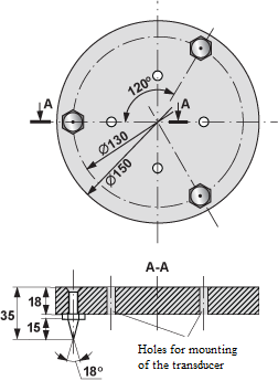
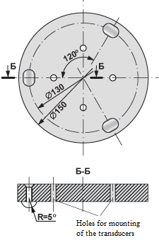
The figures below show dimensional drawings of mounting devices with pointed/rounded legs for triaxial seismic receivers BC 1313 furnished with four mounting holes on the base.
Installation on Hard Surface
Vertical measurements
Installation on a hard surface (building foundation/wall, road pavement, hard floor, window/door) without fastening facilitates vertical measurements within the range up to 100 Hz with acceleration value not exceeding 3 m/s2. With acceleration over 3 m/s2 or in the case of upper frequency of analysis exceeding the range of 100 Hz, the sensor shall be fixed on the surface with bolts, glue, cement, etc. Sometimes it is enough to fix the sensor with just wax.
Horizontal measurements
In the case of installation on hard surface without fastening, the horizontal measuring accuracy is ensured within the frequency range of up to 40 Hz with acceleration not exceeding 3 m/s2. At frequencies over 40 Hz and acceleration values exceeding 3 m/s2, the sensor shall be fixed on the surface with bolts, cement, glue, wax, etc. to prevent its displacement.
Installation on Pliant Surface
Vertical measurements
When installed directly on a pliant surface (carpet, floor covering), the vibration sensor provides measurement accuracy at frequency values not more than 20 Hz. If the vibration sensor is installed on a pliant surface using quick mounting device with pointed legs, the analysis frequency increases up to 100 Hz, with acceleration not exceeding 3 m/s2 in all directions. There are no any special methods required, but the sensor together with the device should weight about 2.5 kg.
Horizontal measurements
If the sensor is installed on a pliant surface using quick mounting device with pointed legs, the measuring accuracy is ensured in a range with 40 Hz upper frequency limit.
Ground Installation
The results of vibration measurement on/in the ground enable only approximate estimation of the building foundation vibration, but can also be used to quantitatively assess the vibration source, for example, to determine the level of seismic effects on the EMS-98 scale. The sensor installation method is selected depending on the required accuracy of measurements and the feasibility of a certain method.
Sensor on a bar
The sensor is mounted on a bar, which is hammered into the ground so that its hard coupling with the ground is ensured. The bar should not deform when hammered. The advantages of this method include low cost and ease of implementation. As for the disadvantages, this method only allows to obtain information on oscillations on the ground surface; has poor reproducibility (especially in the case of horizontal measuring); the results depend on geometry of the bar; this method requires great care when hammering the bar and removing loose soil.
Earthing
It is used for long-term tests. The sensor is earthed, then the soil is compacted. Advantages: good results when measuring the horizontal component of vibration at a given depth. Disadvantages: high probability of significant instrumental error when measuring vertical component of vibration, complexity of implementation (may require a permit for excavation), demanding requirements to water resistance and mechanical strength of sensor.
Sensor in the hole
The sensor is installed in the open hole. In case of loose rock, the installation spot must be located above the groundwater level. In order to assess the potential vibration impact when designing the buildings, the measurements are made in the ground at 1.5 m depth, since the vertical component of vibration at this depth is closest to the one that will occur at this spot on the foundation of buildings. The bottom of the hole is compacted and equipped with a casing pipe, which contains the vibration sensor on the mounting device with three openings and a rope for sensor retrieval from the hole (see the figure on the right). The pipe is removed before measurements. Advantages: good results when measuring the horizontal component of vibration, easier implementation if compared to earthing. Disadvantages: inaccurate results for the vertical component of vibration at depths of up to 1 m; may require a permit for excavation; measurements are possible only at the bottom of the hole; geophone application requires a large diameter hole (up to 0.2 m); poor control over sensor position adjustment at the bottom of the hole.
Sensor on a plate at the ground surface
The sensor is mounted on a plate and fixed in case of a light weight sensor. The sensor plate is mounted on a sand bed and covered with cement. Dimensions and weight of the plate are selected in order to ensure that this set of plate and sensor does not not distort the propagating seismic waves. Also, the plate with sensor installed on the ground should not have resonances in the range of the analyzed frequencies. Advantages: this method provides good reproducibility and does not require costly equipment. Disadvantages: this method only allows to study the oscillations on the ground surface; requires great care when installing and cementing the plate; requires caution when removing loose soil.
Measuring Points
When measuring the vibration of structures, it is important not only to properly install the sensors, but also to select the most informative measuring points. As the seismic wave impacts a structure during earthquakes, vibrations from a passing rail transport, oscillations due to wind load, the different parts of a building are exposed to different loads. In addition, the individual structure elements have their own nodes and antinodes of oscillations at each frequency. Therefore, to analyze the response of the whole structure during the tests, the measurements must be carried out at several points in three directions at once.
When assessing the vibration effects on a building, the sensors are installed on the building’s foundation, load-bearing part on the upper floors, on the floor slabs, on the walls. To estimate the potential effects of vibration when designing the buildings, the measurements are performed on the ground and at the foundations of neighboring buildings.
Measuring Points on Foundation
In order to measure the foundation vibration, the vibration sensor is installed at the foundation or the seamless bearing stone wall, for example, on a basement window jamb, reinforced concrete perron steps. The height of the sensor above the ground shall not exceed 0.5 m. The vibration should not be measured on the hollow structure elements or the elements without rigid link to the foundation.
Measuring Points on the Building Floor
The vibrations of the parts of the building, for example, walls and flooring, should be measured at the points of maximum vibration:
- in the vertical direction — in the middle of the flooring
- flooring with strong beams — between the beams
- transverse horizontal component of vibration of the walls — at the point of intersection of the wall diagonals
- horizontal vibration on the upper floors — near seamless bearing walls or at door/window openings.
Ground Measuring Points
To obtain the estimates, the vibration is measured on the ground surface or in soil near the source of vibration and along its propagation direction. For assessing the power of vibration source, the sensor is mounted near the source at a certain distance (e.g. 5 m from railway) and at a sufficient distance from the massive bodies that may distort the measurement results. It is recommended to ensure that the distance from a measuring point to a massive body is 1.5 times more than its maximum size. If the massive body or soil layer with significantly different dynamic characteristics is on the way of vibration propagation at the measuring point, the possible effects of diffraction and reflection of seismic waves in the soil may cause decreased vibration at this point. And vice versa, a seismic wave reflected from the neighboring building foundations or sewer manholes may reach the measuring point, which will increase vibration level at this point.
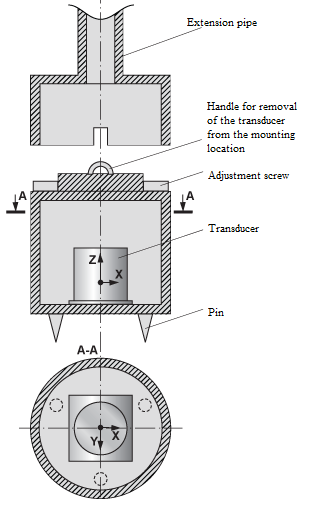
Device for installing sensor in the hole