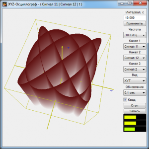
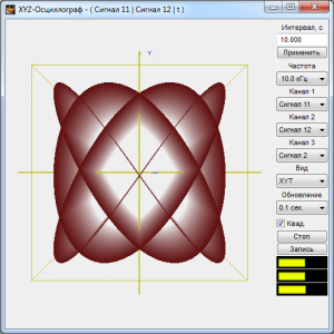
XYZ Oscillograph
XYZ Oscillograph is a program assessing signal forms and displaying signal parametric dependence.
SUPPORTED HARDWARE
Input data for XYZ Oscillograph includes digital data of the ZETLAB server channel.
XYZ Oscillograph is a part of the following software:
- ZETLAB BASE — ADC/DAC board software;
- ZETLAB ANALIZ — spectrum analyzer software;
- ZETLAB VIBRO — vibration bench control system software;
- ZETLAB TENZO — strain-gauge station software;
- ZETLAB SEISMO — seismic station software;
- ZETLAB NOISE — vibration meter-noise meter software;
- ZETLAB SENSOR — digital ZETSENSOR sensor software.
XYZ Oscillograph is included in the Display software group.
XYZ Oscillograph Description
Display Interval and Data Representation Frequency
The box under Interval, c is used for entering signal ratio display time interval (horizontal scan). The maximum and minimum intervals are determined by the selected frequency band of the displayed signal ratios. The greater the frequency band, the greater the volume of processed data, and the lesser the signal ratio display time interval; accordingly, the lesser the frequency band, the lesser the volume of processed data, and the greater the signal ratio display interval. Interval values are entered from the keyboard after the cursor is placed in the entry box. To set the entered time interval, it is necessary to click Apply under the interval entry box or the key on the keyboard.
The button Apply is used for setting the entered time interval as well as restoring the original scale of the time axis data.
Under Frequency, Hz in the list, a frequency band for the displayed signal ratios is selected. To select a desired frequency band, it is necessary to left click on the list button and select a desired frequency band in the drop-down list. The frequency band is determined by the discretion frequency set in ZET Device Manager.
Selecting Measuring Channels
Under Channel 1 in the list, a channel for displaying X plane views in diagrams is selected.
Under Channel 2 in the list, a channel for displaying Y plane views in diagrams is selected.
Under Channel 3 in the list, a channel for displaying Z plane views in diagrams is selected.
Display Option
Under View in the list, a display mode is selected: ХТ, YТ, ZT, ХY, YZ, XZ, ХYТ, YZT, XZT, XYZ.
- Diagrams of the XТ, YT, and ZT views are time realizations (oscillograms) of Channel 1, Channel 2 and Channel 3, respectively.
- The XY view diagram is a parametric curve, where x=X(t) and y=Y(t), on the XY plane – a Lissajous figure.
- The XZ view diagram is a parametric curve, where x=X(t) and z=Z(t), on the XZ plane – a Lissajous figure.
- The YZ view diagram is a parametric curve, where z=Z(t) and y=Y(t), on the YZ plane – a Lissajous figure.
- The XYT view diagram is a parametric curve, where x=X(t), y=Y(t), in a three-dimensional view in the XYT space – a three-dimensional Lissajous figure.
- The XZT view diagram is a parametric curve, where x=X(t), z=Z(t), in a three-dimensional view in the XZT space – a three-dimensional Lissajous figure.
- The YZT view diagram is a parametric curve, where z=Z(t), y=Y(t), in a three-dimensional view in the YZT space – a three-dimensional Lissajous figure.
- The XYZ view diagram is a parametric curve, where x=X(t), y=Y(t), z=Z(t), in a three-dimensional view in the XYZ space – a dynamic Lissajous figure.
The flag Sq. is used for scale alignment on the X and Y axes. When the button is pressed, aligning takes place, when released – no aligning.
Display Start/Stop
The Start button starts continuous signal display, and the accumulated data is set to zero, and the button name changes to Stop.
The Stop button stops continuous signal display, and the button name changes to Start.
Recording Results
The Record button is used for recording the data accumulated in a set interval in a *.dtu text file.
Signal Level Indicators
The indicator Integral level presents the signal integral level for each channel and, when the maximum admissible level is surpassed, the congestion of the corresponding channel. Two thirds of the indicator’s field are used for the signal level, not surpassing the maximum admissible level. The higher the level, the more the indicator is filled. When the maximum admissible level is surpassed, the indicator is filled with red completely. The right edge of the indicator remains red until the channel congestion is not reset and the user clicks on the indicator with the left mouse button. The number of indicators corresponds to the number of open oscillograms.


