
Lift positioning
and movement parameters control by means of inertial navigation methods
Inertial system of elevator car movement control is represented by hardware and software complex based on classical laws of mechanics. Inertial navigation is a method for determination and control of coordinates and parameters of various objects movement. The system is based on inertial properties of the objects and it is standalone, i.e. no external guidelines or signals are required.
In inertial navigation systems, the main reference system (in relation to which the measurements are performed) is represented by an inertial system, which has relatively stable properties. The inertial navigation system is used to coordinates, velocity, acceleration and other basic properties of object’s movement.

Among the advantages of inertial navigation, one should mention its independence, interference protection and full automation of all navigation processes. These very features make the inertial navigation systems the most widely applicable solution.
Inertial navigation system operating principle is based on the determination of lift car movement parameters. Elevator car movement can be characterized by such parameters as acceleration, velocity, and relative displacement. Elevator car movement in the inertial coordinate system can be described by the following equation:
![]()
where ω — acceleration value controlled by the accelerometer; rm — radius vector of М point (sensing element gravity center) in the inertial coordinate system; F — sensing element mass unit gravity force at М point (gravity acceleration).
Movement control method is based on measuring the velocity value of elevator car. Acceleration value can be measured by a special sensor – the accelerometer. Then it is necessary to perform digital processing of the analog signal obtained by means of FFT spectrum analyzer based on ADC conversion method. After that, the digital data undergoes further processing (e.g., by means of PC). Post-processing of the acceleration signal is performed by means of a mathematical tool. After having calculated the source acceleration signal integral value, we shall have elevator cabin velocity value and by integrating the source signal twice, it is possible to obtain relative displacement value of the lift cabin (i.e. its coordinates).
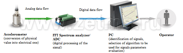
Data flow from sensor to operator
Practical implementation of inertial navigation has certain difficulties, for instance, it is necessary to use gyro or electromechanical integrators, while our system has a relatively simple structure of signal processing (sensor-ADC-PC). At the same time, it is necessary to provide high precision and reliability of all the components taking into consideration dimensional and weight parameters. It is possible to overcome these difficulties by means of task-specific hardware and software complex – the inertial navigational system.
Depending on particular features, it is possible to classify the navigational systems into several groups:
- depending on sensing axes orientation:
- arbitrary orientation;
- celestial guidance;
- orientation of axes in direct relation to the controlled object;
- with constant orientation by a celestial body (e.g., by the Earth);
- horizontal, etc.;
- by vertical loops:
- with analytical or calculated vertical loop;
- with the inertial calculation of vertical loop;
- by the presence of steady platform:
- with steady gyro or astro platform;
- without a steady platform, etc.
Classical inertial navigation systems are quite complex and expensive. Their lifetime is shorter than that of standard gyro instruments. For the purpose of inertial navigation system stable operation it is necessary to provide initial coordinates and velocity data and to perform orientation of inertial measuring instruments prior to starting the system. Simplicity and reliability of inertial navigation system measurements are attributed to several factors:
- simplicity and reliability of the system due to a small amount of structural components;
- modular structure of the system;
- possibility of full automation of measurements and control functions;
- metrological properties of the system’s measuring components;
In order to establish a simple inertial navigation system, it is enough to have PC (laptop), FFT spectrum analyzer or ADC DAC module and accelerometer.
The accelerometer is an instrument that measures the constant component of elevator car acceleration. Modern accelerometers allow to measure acceleration value in three axes. The accelerometer can be used for measuring both linear and gravity acceleration (this very feature is implemented in tiltmeters). Accelerometers are included in the scope of inertial navigation systems, in which the measured results obtained are integrated, thus allowing to find inertial velocity and coordinates values. We suggest using accelerometer BC201 in this system (it is a capacitive accelerometer that can be used both as a linear acceleration sensor and position sensor since it measures both alternating and constant component of acceleration signal). When installing accelerometer BC201 on a sloped surface, it can be used for measuring centrifugal acceleration value.
Accelerometer BC201 is perfectly suitable for creation of inertial navigation systems. Together with ADC DAC module ZET 220, connected to PC, sensor BC 201 forms a compact system with a wide application range.
Operating principle of FFT spectrum analyzer (ADC – DAC module)
From operational point of view, Figure 1 can be represented as “measurement and instant display of the result”:
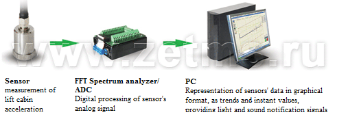
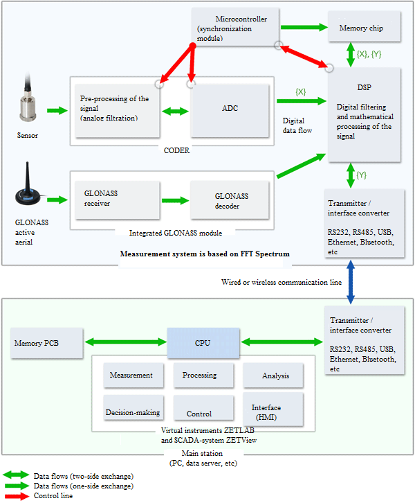
Simplified functional scheme of hardware-software system
Accelerometer BC201 is fixed in vertical position inside of the elevator car. Then it is connected to ADC-DAC module ZET220 switched to PC (laptop). Measurement data processing is performed by means of a turn-key solution integrated into SCADA-system ZETView (program “Inertial navigation system” (algorithm description)). Use of SCADA-system allows the user to edit process automation logics as well as to change the program overview, if necessary.
Elevator car movement parameters: measurements results
Below you can see two figures showing program operation results – elevator car movement upstairs (left) and downstairs (right).


Upon completion of several experiments (measurements of elevator cabin speed during upwards and downwards movements, there has been calculated an error ratio of 0,5% of measuring sensor’s fundamental frequency, that is equal to 0.0002 g). In the course of elevator cabin travel to the 21-st floor, there have been obtained values specified in figures 7 and 8. Besides, an additional advantage of the system is represented by the possibility of measuring process visual representation. At the graphs above one can clearly see points of elevator cabin acceleration and stop. This allows analyzing all the transient processes that occur during start and stop of lift’s cabin movement.