Connection of ZET017 U4/U8/T8 via Ethernet
Introduction
The present article describes the network protocol which is used for connection to FFT Spectrum analyzers and Strain-gauge stations ZET017 U4/U8 /T8 manufactured by Zetlab Company.
By “device” in the present article, there is meant FFT Spectrum analyzer or Strain-gauge station ZET 017 U4/ U8/ T8 and by “client” we mean a PC or any other instrument that is connected to a device used for control or data exchange with ADC/ DAC modules.
Operating principles of the device
The device can operate in one of the following operating modes
1. USB connection.
2. Ethernet connection.
3. Standalone recorder.
The USB mode is always available while the Ethernet mode and Standalone recorder mode are available as additional options. For the purpose of Ethernet mode operation, there is used a protocol, which is further described in the present document. The protocol operates in parallel with the transport protocol TCP/IPv4 in server mode (i.e., the device does not establish connection automatically and the connection is established by the client). Before using the device in Ethernet mode, it is necessary to configure the network interface parameters. Configuration of the network interface is performed in the USB mode with the use of ZETLAB software programs.
Network interface parameters:
- address IPv4;
- subnet mask;
- network gateway address;
- TCP/IPv4 port number;
- duplex/ half-duplex mode (normally the duplex mode is used);
- speed 100 Mbps or 10 Mbps (normally 100 Mbps).
The Ipv4 address should be set statically since the device does not support the DHCP/BOOTP protocols for automated detection of the address. The parameters by default are as follows: address: 192.168.0.100, subnet mask: 255.255.255.0, gateway: 192.168.0.1. TCP/IPv4 port number is available in settings, however, only the value “1808” is used.
TCP/IPv4 ports
The device activates three TCP/IPv4 ports:
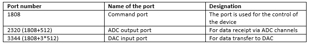
The command port is a two-way port: the client is using it to send the commands and the device is using it to send the response to commands. ADC and DAC ports are represented by one-way ports. They are used for ADC data transfer from the device to the client and for DAC data transfer from the client to the device respectively.
Format of the command packages
Commands
The first two bytes of the command packages contain the code of the command. The content of the remaining 1022 bytes depends on the code of the command.
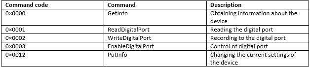
The tables below display the types of the fields to be used for setting the digit capacity. The “Control” column allows to determine whether the field is configurable (R/W — read/write) or not (R/O — read-only).
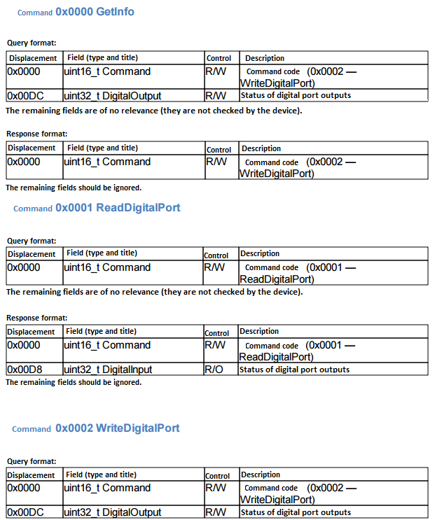
The remaining fields are of no relevance and they are not checked by the device.
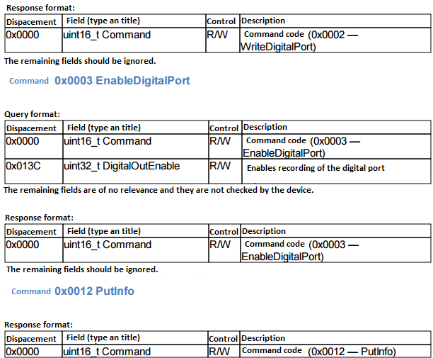
The remaining data of the command package correspond to the response to the query 0x0000 GetInfo.
Prior to sending the query package, it is necessary to check the current settings using the command 0x0000 GetInfo and then to change the contents of particular fields. The field R/O cannot be changed. The response format corresponds to that of the response to the command 0x0000 GetInfo, the command code is also identical (Command == 0x0000).
Connection to the device
Connection to the device:
- Connection to the device is conducted in several stages.
Establishing connection TCP/IPv4:
- The client should establish a connection via the protocol TCP/IPv4 to all three ports of the device. The connection sequence is of no relevance.
The address IPv4 should be available for the device beforehand since the device cannot find it in the local network by means of broadband or group queries (such as for instance, SNMP).
Conditioning:
As the connection to a port is established, the device sends to the customer a package for conditioning.
This data does not contain any important information – it is only used for conditioning with the device.
Initialization:
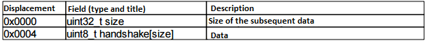
Upon completion of the conditioning process, it is necessary to conduct initialization. To do that, send two commands via the command port: 1. 0x0000 GetInfo — to get information about the device. 2. 0x0012 PutInfo — to conduct initialization of the device.
Control of the device:
Upon completion of initialization, it is possible to use the device. The command port is used for sending the commands that allow to change settings, to control the digital port of the device, and to switch ADC or DAC on/off. If the connection is lost at any of the ports, the device will switch off the remaining ports and suspend the operation of ADC and DAC. After that, the device will activate the standby mode until a new connection is established. The connection loss is detected as the patch-cord is disconnected (link down) or via TCP Keep-Alive.
Receiving ADC data
Configuration of ADC channels
Prior to obtaining data from ADC, it is necessary to conduct configuration of ADC channels. To perform the configuration, use the command PutInfo. The “Info” parameter is always available in the device. The number of channels is indicated as “QuantityChannelsADC” (4 or 8).
A channel can be enabled or disabled (however, at least one channel should be enabled). Also, a channel can be used in ICP mode or without it. The field “Info” allows to enable/ disable a channel. The field “ChannelADC” containing bits # 0-7 is used to control the state of a particular channel. For instance, to enable the channels 1,2 and 4, the field should display the value Info.ChannelADC == 0x000B (bits # 0,1 and 3 are set). The total number of active channels is specified in the field “Info.WorkChADC”. In the case, if channels #1,2 and 4 are enabled, the field displays the value “3”. Th ICP mode is controlled by the field “Info.ICPChannel”, containing bit mask for each of the channels. The channels perform synchronous digital processing of the data and have a common sampling frequency value.
The frequency is controlled by the field Info.ModaADC:
- 50 kHz (Info.ModaADC == 1);
- 25 kHz(Info.ModaADC == 2);
- 5 kHz (Info.ModaADC == 3);
- 2 500 Hz (Info.ModaADC == 4);
- 25 kHz (by default for all other values – Info.ModaADC).
It is also possible to set the amplification ratio for each of the channels using the array “Info. CodAmpllify”:
- AR 1 (Info.CodAmplify[i] == 0, by default);
- AR 10 (Info.CodAmplify[i] == 1);
- AR 100 (Info.CodAmplify[i] == 2);
Starting the ADC
In order to start the ADC (upon completion of channels configuration), it is necessary to send the command “PutInfo” where the field “Info.StartADC” has the value “1”.
Data acquisition
The data are transferred via ADC port (as soon as they are available) only in the case if the ADC is enabled (Info.StartADC == 1). The data is transferred in batches of 1024 bytes. The first 1008 bytes contain a group of reports. The reports are transmitted in frame-by-frame mode – i.e. as groups containing a single report from each of the active channels.
E.g., if the channels #1, 2 and 4 are enabled, then the data will be transferred in the following sequence:
- [report №1 of channel 1], [report №1 of channel 2], [report №1 of channel 4];
- [report №2 of channel 1], [report №2 of channel 2], [report №2 of channel 4];
- [report№3 of channel 1], [report v№3 of channel 2], [report №3 of channel 4];
- and so on.
Each report is transmitted in “raw” format int16_t (2 bytes) or long (4 bytes) depending on the digit capacity of the ADC used in the device (Info.TypeDataADC). The bytes 1008-1015 are not used and should be ignored. The last 8 bytes (# 1016-1023) contain a batch counter incremented by 1 or each of the transferred packages. The batch counter is used for the control of packages sequence.
Suspending operation of the ADC
In order to suspend operation of the ADC, use the command with the field “Info.StartADC == -1” (query for suspension of ADC operation). As the command is sent, it is necessary to continue reading of the packages received via ADC until the device sends a zero package (containing 1024 zero bytes). Then it is necessary to send the command with the field “Info.StartADC == 0” (complete suspension of ADC operation).
Operation of the generator
Configuration of generator parameters:
The device has only one generator channel. The command “PutInfo” is used to change the parameters configuration.
The ADC sampling frequency is adjusted with the use of the command “Info.RateDAC”:
- 200 kHz (Info.RateDAC == 400);
- 100 kHz (Info.RateDAC == 800);
- 50 kHz (Info.RateDAC == 1600);
- 25 kHz (Info.RateDAC == 3200).
It is possible to set values of “Info.RateDAC” parameter, that are different from those specified in the above chart, however, it may lead to faults in operation of the generator. The resulting sampling frequency is calculated by the formula: “FreqDAC = RefFreqDAC / RateDAC”, where RefFreqDAC == 80 MHz.”
Starting the generator
The start of DAC is synchronized with the start of ADC. Thus, to start the DAC, it is necessary to send the command “PutInfo” containing the field “Info.StartDAC == 1”, and then to start the ADC.
Generator data submission
The device receives DAC packages only in the case if the generator is enabled (Info.StartDAC == 1). The DAC package contains 10214 bytes with 512 counts of DAC in “raw” format int16_t (2 bytes). One should bear in mind that DAC data are produced at the hardware output of the generator with a certain delay from the moment of their submission, thus, the data should be sent in advance. The device also has a data buffer for DAC data accumulation. The device receives the new data via DAC port only when the data buffer has free space. As the data buffer is filled, the data receipt will be suspended until the buffer memory is released as the data is transmitted via output of the generator. The device can send the data via DAC port. The data contents should be controlled in order to avoid output buffer trashing. This data can be ignored.
Suspenion of generator’s operation
In order to suspend operation of the DAC, send the command “PutInfo” with the field “Info.StartDAC == -1” and then the command “PutInfo” with the field “Info.StartDAC == 0”.
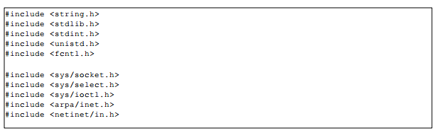
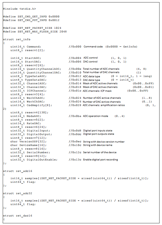
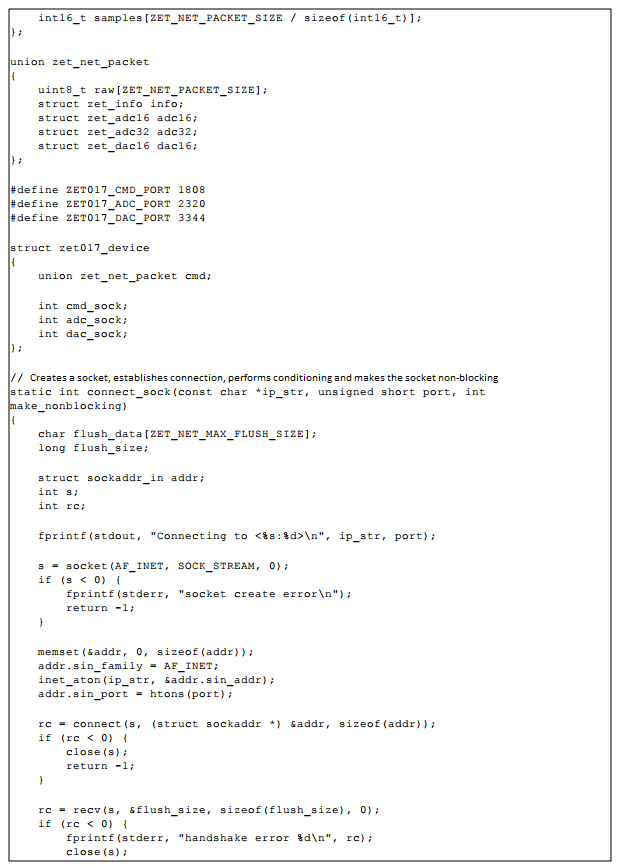
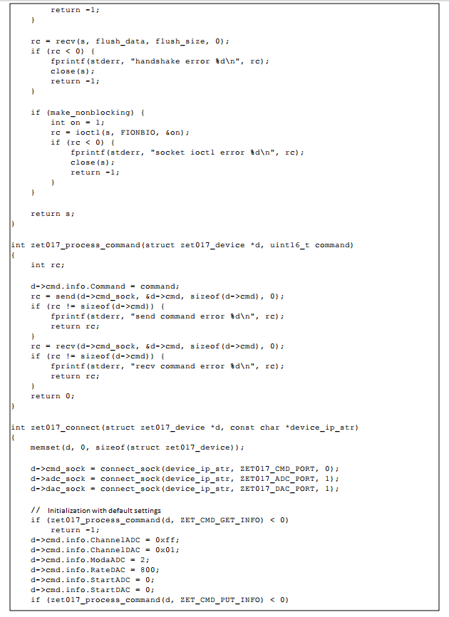
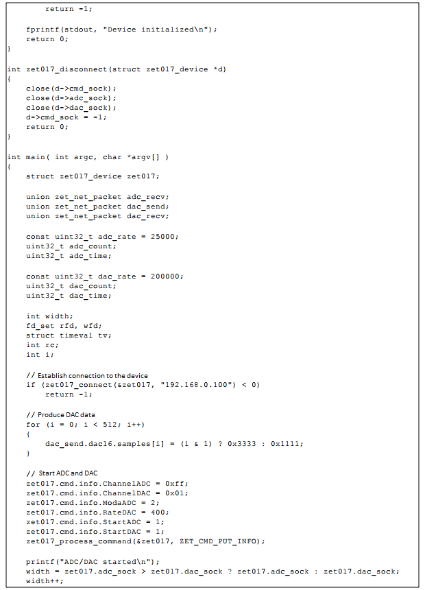
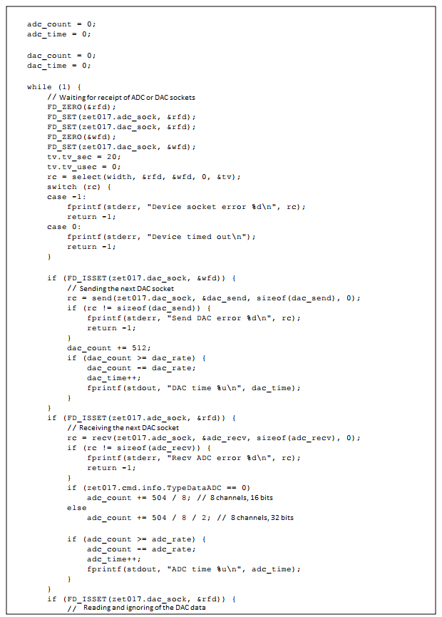
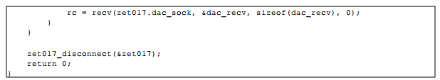
An example of the program
Below you can see an example of a simple program. The program connects to the device with IP-address 192.168.0.100, starts the ADC (8 channels, 25 kHz) and the DAC (200 kHz) and produces one message per second.