
Configuring operation modes
of the ZETLAB digital sensors with the RS-485 interface using the SensorWork tool
In most cases, configuring the ZETSENSOR units with the RS-485 interface is performed using the standard ZETLAB software, in the Device Manager on the “Service” tab. This requires the ZET 7070 or ZET 7076 interface converter.
However, some practical tasks require operation of the ZET 7xxx sensors through other interface converters and relevant changes in the digital sensors configuration without the use of the standard ZETLAB software. Generally, all such converters can function as COM ports. For operating through a COM port, there is a special tool SensorWork, which allows data exchange with the digital sensors and accordingly their configuration without the ZETLAB software installation.
A sensor configuration using SensorWork is perfomed in the following way:
SAVING THE CURRENT SENSOR CONFIGURATION TO A FILE
For each digital sensor, SensorWork creates a so-called “snapshot” of settings which represents a file with .dat extension and binary contents (see Figure 1). A file is created automatically for each device when it is found by the program. All files are saved to the following path: “SensorWork.exe_Location_DirectorySensorWorkConfigurationBackupYYYY_MM_DD”, where YYYY_MM_DD is the current date. The name of such a file has the format like “ZET 7AAA № 0xBBBBBBBBBBBBBBBB_C.dat”, where 7AAA is the type (e.g. 7021), BBBBBBBBBBBBBBBB, serial number in hexadecimal format (e.g. 2b0c575b5a2f0922), C, device address (e.g. 4). The contents of the file fully match the contents of the measuring unit registers.
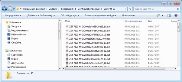
Figure 1READING THE SENSOR REGISTER ADDRESS TABLE
In order to understand which register contains the required information, SensorWork uses an option to read the register address table. The table is generated as shown in Figure 2. A part of the address table is shown in Figure 3.
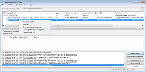
Figure 2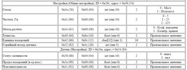
Figure 3MODIFYING THE CONFIGURATION FILE
When the file with the current sensor configuration and its address table are available, it is possible to alter a required parameter and receive a file with new configuration. For example, the frequency value is at 0x3c address (see Figure 3), it is of integer (int) type (4 bytes in size) and may take values of 0 (5 Hz), 1 (25 Hz) or 2 (125 Hz). So, in order to set the required frequency, the contents of the current configuration file should be altered as follows: first, move 2 bytes from the beginning on 0x3c, then convert the following 4 bytes to int and change the value to 0, 1, or 2 (depending on the required frequency). After editing, a new configuration file is obtained with the required parameters.
RESTORING THE CONFIGURATION USING THE MODIFIED FILE
To write the changed configuration file to the sensor, the configuration restore option is used. It is used as shown in Figure 4. Select the modified file as the image for restoration.
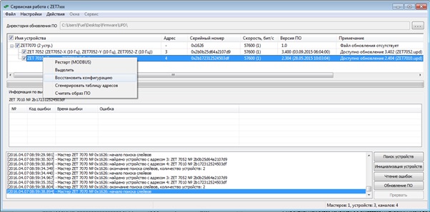
Figure 4